


Hardware components | ||||||
 |
| × | 1 | |||
 |
| × | 1 | |||
| × | 1 | ||||
| × | 1 | ||||
| × | 1 | ||||
| × | 1 | ||||
| × | 1 | ||||
| × | 1 | ||||
| × | 1 | ||||
 |
| × | 1 | |||
Software apps and online services | ||||||
 |
| |||||
Hand tools and fabrication machines | ||||||
| ||||||
 |
| |||||
 |
| |||||
We know that many countries has its own disputes with their neighboring countries regarding maritime security.
Generally people cross the maritime border with or without their knowledge for a purpose which gives rise to illegal entries. Incidents like firing at fishing boats by the Navy ,violating immigration law by crossing the borders, arresting people due to boundary crossing etc.. has led to great deal of suffering among the fisherfolk and other sea vehicles of both countries.
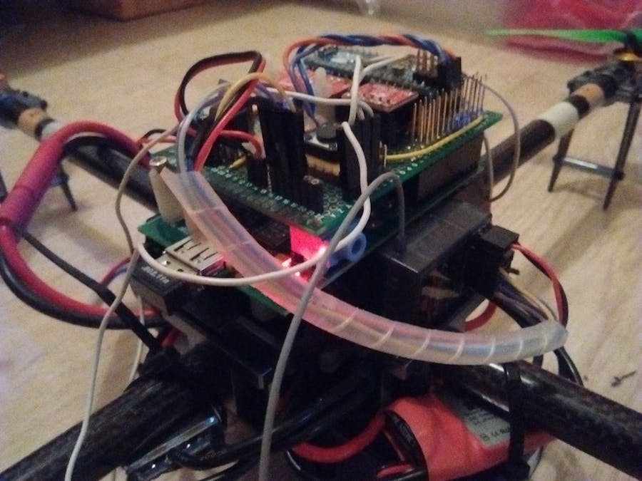
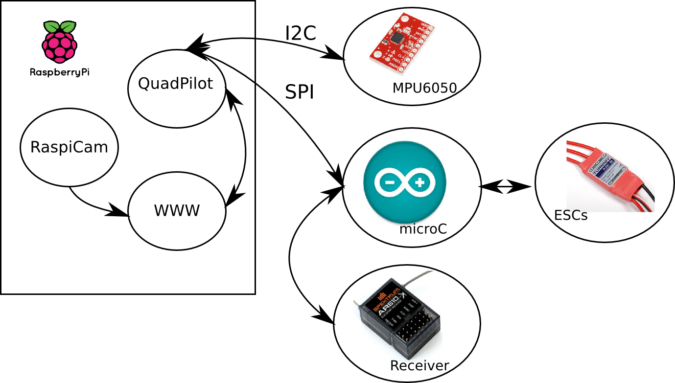
Technical working of MAD-10:To overcome the above motioned problems, we are building a Quad-copter named MAQ-10(Micro Aerial Quadcopter-10) which is controlled by a Raspberry pi-2 (I used an Rpi since i do not have two creator ci20 boards.... an alternative). The RPI will hold the PID, but a micorcontroller is used to interface the RC receiver and the ESCs. The Rpi aks the microcontroller for RC commands and sends motor speed values through I2C. An Arduino Micro has been chosen as microcontroller, for its compact size and sufficient abilites for the job.
Host (The Raspberry PI):- PID controller
- Web interface to access the Camera (work in progress but i have uploaded the source code and other related files which i have been working for the interface till now :-)
- Communication with the MPU6050 through I2C.
- Communication to Arduino Micro through SPI
PRINCIPLE
Wiring
- MPU6050 -> RPI : -VDD -> 3.3V -GND -> GND -SDA -> SDA -SCL -> SCL -VIO -> 3.3V
- Arduino -> RPI : -VCC -> 5V from external Regulator -GND -> GND -MISO -> Logic Level converter ->MISO -MOSI -> Logic Level converter ->MOSI -SCK -> Logic Level converter ->SCK
ESCs and RC Receiver on Arduino:
- Using PinChange interrupts
- Check in the Arduino code.
I have also uploaded the files for ServoBlaster that I use to control the ESCs and the MPU6050 Digital motion processing and for the Timing and the code structure separately.
Client (Creator Ci20):At receiving end we use Creator Ci20 board, since it has very a powerful processor with other cool and attractive features and also inexpensive when compared to computers we are using it as an alternative for PC's. Using Open CV installed on the Ci20, we can detect marine vehicles using object detection algorithms from the live video feed received from the Quad , fly it closer and take snap shots of the intruder's vehicle and make use of speakers to alert them
Receiver end object detection based on openCV and zeromq framework:Requirements
- Opencv (python) as cv (opencv) and cv2 (numpy)
- Zeromq (python)
- Gevent (light weight switch)
- Knowledge about img process
- Profile, logging each stage mem and cpu time
Server
- capture img
- send img to clinet
- wait for next command from client
- update status by new command
Client
- receive img
- run all detection
- build up a new command, based on detection results
Detections
- face detect
- circle detect
- line detect
- find attribute obj
Running It
- python poll_camera.py (using cv to capture/show img via remote protocol)
- python poll_camera2.py (using cv2 to capture/show img ...)
- python poll_thread_run2.py (using cv2 to run all thread detection based on CPU num)
- python poll_series_run2.py (using cv2 to run all series detection ...)
1) build the MAQ-10 (Mechanical) body.... beginers follow this instructables http://www.instructables.com/id/Basic-Quads-Systems-My-Easy-Quad-Build/
2) Refer the Principle and perform the wiring as per the given details and build the qudcopter
3) Install the required softwares and packages in both the Rpi and Ci20
4) Use the files uploaded here on those boards. if required, modify it according to your needs :-)
5) Fly the Quad using the remote and the live images will be received on the Ci20 board and processed using open CV
lnstalling Open CV:Please Visit https://mipsci20.wordpress.com/ for step by step instructions to install open CV on Ci20.
Please Visit http://www.pyimagesearch.com/2015/02/23/install-opencv-and-python-on-your-raspberry-pi-2-and-b/ for step by step instructions to install open CV on RPI-2
How to fly the drone:Please Visit http://uavcoach.com/how-to-fly-a-quadcopter-guide/ for the ultimate guide.....very useful :-)
Future Work:The cameras installed should be used for navigation of the drone (Autopilot) hence we can approach the vehicles before crossing the border and alert them, simultaneously snapshots of the scene are captured and sent to the coastal guards, but right now using the camera feed from MAQ-10 we are manually controlling it.
Docking stations are being built certain spots for charging MAQ-10 and dock to dock patrolling can be performed at regular intervals and various stabilization algorithms are used for accurate flight and for night time surveillance
Instead of using the web camera to get the live feed, we could make use of (SWIR) Short Wave Infrared Night Vision Camera Systems in which images are not in color, This makes objects easily recognizeable but its expensive and heavier.
Conclusion:- Maritime Disputes of a country can be reduced
- illegal entries are prevented
- sea vehicles are warned when they are closing the border
- We can scan wider area, zoom in target and also efficient during night
- risk free surveillance
Thank you for your attention to this Project.
Host side(Quadcopter) Wiring
Arduino -> RPI : -VCC -> 5V from external Regulator -GND -> GND -MISO -> Logic Level converter ->MISO -MOSI -> Logic Level converter ->MOSI -SCK -> Logic Level converter ->SCK
ESCs and RC Receiver on Arduino: -Using PinChange interrupts -Check in the arduino code


_3u05Tpwasz.png?auto=compress%2Cformat&w=40&h=40&fit=fillmax&bg=fff&dpr=2)
Comments