This was actually a summer project which we planned in our college. We are a team of Four, Myself ( Akash), Keerthana, Deepthi and our MENTOR: Krishna Anna.
Software Installations:DAY ONE: We started with the basics of Opencv. Learnt the concepts of image processing. Tried some Basic Codes. I will now show you how to set up the working environment.
- Install Python from Here
- Install Opencv Library for Python from Here
These two things are important for image processing.
Two Workload:- Opencv Image Processing Part
- Mechanical Part
DAY TWO: We tried implementing some code for Opencv for our basic understanding. We then separated the colours based on their hsv value. To know more about hsv, rgb you can always google it. Really Interesting topics.
Code for Tracking the Colour in HSV scale is given below or can be copied from Here.
import numpy as np
import cv2
cap = cv2.VideoCapture(0)
def nothing(x):    #used in trackbars
  pass
cv2.namedWindow('Trackbar')
cv2.createTrackbar('Hl','Trackbar',0,255,nothing)
cv2.createTrackbar('Sl','Trackbar',0,255,nothing)
cv2.createTrackbar('Vl','Trackbar',0,255,nothing)
cv2.createTrackbar('HU','Trackbar',0,255,nothing)
cv2.createTrackbar('SU','Trackbar',0,255,nothing)
cv2.createTrackbar('VU','Trackbar',0,255,nothing)
##hl=0
##sl=0
##vl=0
##hu=255
##su=255
##vu=255
##
##cv2.setTrackbarPos('Hl','Trackbar',hl)
##cv2.setTrackbarPos('Sl','Trackbar',sl)
##cv2.setTrackbarPos('Vl','Trackbar',vl)
##cv2.setTrackbarPos('HU','Trackbar',hu)
##cv2.setTrackbarPos('SU','Trackbar',su)
##cv2.setTrackbarPos('VU','Trackbar',vu)
while(True):
  # Capture frame-by-frame
  ret, frame = cap.read()
  if(ret==0):
      continue
  hsv = cv2.cvtColor(frame, cv2.COLOR_BGR2HSV)
  hl=cv2.getTrackbarPos('Hl','Trackbar')
  sl=cv2.getTrackbarPos('Sl','Trackbar')
  vl=cv2.getTrackbarPos('Vl','Trackbar')
  hu=cv2.getTrackbarPos('HU','Trackbar')
  su=cv2.getTrackbarPos('SU','Trackbar')
  vu=cv2.getTrackbarPos('VU','Trackbar')
  upper=(hu,su,vu)
  lower=(hl,sl,vl)
  print np.shape(hl)
  # Our operations on the frame come here
  cnv = cv2.inRange(hsv, lower,upper)
  # Display the resulting frame
  cv2.imshow('output',cnv)
  cv2.imshow('frame',frame)
  if cv2.waitKey(1)==27:
      break
# When everything done, release the capture
cap.release()
cv2.destroyAllWindows()
EndFragment
DAY THREE: Now after we have tracked the colour of an object, our next step was to trace it. We thought of several ideas. Then concluded with a simple concept of joining the previous points and the present points.
It was actually a pretty simple concept, JOINING POINTS. We struggled a lot to guess this simple concept.
DAY FOUR: Implemented that code and made it to track the object movement.
Code for Tracing a coloured Ball is given below or can be copied from Here.
# import the necessary packages
from collections import deque
import numpy as np
import argparse
import imutils
import cv2
# construct the argument parse and parse the arguments
ap = argparse.ArgumentParser()
ap.add_argument("-v", "--video",
  help="path to the (optional) video file")
ap.add_argument("-b", "--buffer", type=int, default=64,
  help="max buffer size")
args = vars(ap.parse_args())
# define the lower and upper boundaries of the "green"
# ball in the HSV color space, then initialize the
# list of tracked points
greenLower = (34, 0, 170)
greenUpper = (124, 41, 255)
pts = deque(maxlen=args["buffer"])
# if a video path was not supplied, grab the reference
# to the webcam
if not args.get("video", False):
  camera = cv2.VideoCapture(0)
# otherwise, grab a reference to the video file
else:
  camera = cv2.VideoCapture(args["video"])
# keep looping
while True:
  # grab the current frame
  (grabbed, frame) = camera.read()
  # if we are viewing a video and we did not grab a frame,
  # then we have reached the end of the video
  if args.get("video") and not grabbed:
      break
  # resize the frame, blur it, and convert it to the HSV
  # color space
  frame = imutils.resize(frame, width=600)
  # blurred = cv2.GaussianBlur(frame, (11, 11), 0)
  hsv = cv2.cvtColor(frame, cv2.COLOR_BGR2HSV)
  # construct a mask for the color "green", then perform
  # a series of dilations and erosions to remove any small
  # blobs left in the mask
  mask = cv2.inRange(hsv, greenLower, greenUpper)
  mask = cv2.erode(mask, None, iterations=2)
  mask = cv2.dilate(mask, None, iterations=2)
  # find contours in the mask and initialize the current
  # (x, y) center of the ball
  cnts = cv2.findContours(mask.copy(), cv2.RETR_EXTERNAL,
      cv2.CHAIN_APPROX_SIMPLE)[-2]
  center = None
  # only proceed if at least one contour was found
  if len(cnts) > 0:
      # find the largest contour in the mask, then use
      # it to compute the minimum enclosing circle and
      # centroid
      c = max(cnts, key=cv2.contourArea)
      ((x, y), radius) = cv2.minEnclosingCircle(c)
      M = cv2.moments(c)
      center = (int(M["m10"] / M["m00"]), int(M["m01"] / M["m00"]))
      # only proceed if the radius meets a minimum size
      if radius > 10:
          # draw the circle and centroid on the frame,
          # then update the list of tracked points
          cv2.circle(frame, (int(x), int(y)), int(radius),
              (0, 255, 255), 2)
          cv2.circle(frame, center, 5, (0, 0, 255), -1)
  # update the points queue
  pts.appendleft(center)
      # loop over the set of tracked points
  for i in xrange(1, len(pts)):
      # if either of the tracked points are None, ignore
      # them
      if pts[i - 1] is None or pts[i] is None:
          continue
      # otherwise, compute the thickness of the line and
      # draw the connecting lines
      thickness = int(np.sqrt(args["buffer"] / float(i + 1)) * 2.5)
      cv2.line(frame, pts[i - 1], pts[i], (0, 0, 255), thickness)
  # show the frame to our screen
  cv2.imshow("Frame", frame)
  key = cv2.waitKey(1) & 0xFF
  # if the 'q' key is pressed, stop the loop
  if key == ord("q"):
      break
# cleanup the camera and close any open windows
camera.release()
cv2.destroyAllWindows()
EndFragment
With this, we completed our image processing part.
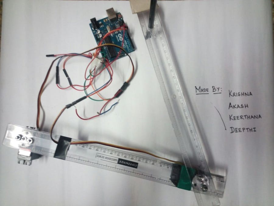
Mechanical Part: Robotic ArmDAY FIVE: With all the needed components, we began our work. We used Hitec HS485HB Servo. We designed a basic design of how we are going to setup the arm. Using two scales our idea was fulfilled. Didn't spend much for the hardware, HAha!
By fitting the servo as shown in the below photo, we tested how much space the servo can cover. Possibly we couldn't cover much area. Next our aim was to fit in the webcam frame 640*480 to the arm sweepable area.
DAY SIX : This was a tough task as we don't know the full potential of the arm. On this day we also made a setup to settle the base servo firmly to the ground.
Next we understood that in order to make the arm move, we have to feed in angles. That is where INVERSE KINEMATICS comes into play. So we studied the inverse kinematics and derived a trignometric formula to convert the points to an angle.
We then tested it by means of this code. To our surprise it worked really good. Seriously, To be frank, We struggled here a lot. Because deriving and implementing the formulas weren't easy. And there wasn't much tutorials to help us.
We then fed some random x,y points and saw the angle output.
DAY SEVEN: Next task for us was to draw a straight line using this setup. We fed the points in an loop fashion incrementing it by one for each loop.
- MISSION ACCOMPLISHED, we drew a line. We did it. Drawing a line is some difficult task for this arm as it actually moves by means of angles. You understand what I mean!
DAY EIGHT: Making the 640*480 match to 28*21. A simple mathematics, since my hypotenuse cant be more than 40, so I scaled down the value to 35, which then produces 28 and 21 as the length of other two sides. We did this because our arm should fit in perfectly within the drawing area.
Not only we have to do this but also some concepts like ROTATION AND TRANSLATION needs to be applied for the drawing area to be easily fitted in.
DAY NINE: We then made some mathematical changes in the code and looked whether the conversion is correct. So what i mean here is, If i draw something in front of the webcam it gives me value in range of 640 and 480.
- Convert it to 28*21
- Apply a origin shifting to 16,23 (this is in my case).
- Apply a rotation shift by 129 degrees. (this is in my case).
If you understand the concepts of origin shifting and rotation, you can very well play with it. Sometimes it is hard to understand.
DAY TEN: We then used the serial communication to send the values from python to arduino by means of Pyserial. It had some difficulties because we were not able to give more speed when it is happening by serial communication although we set the baud rate as 250000.
The code can be seen below or copied from Here.
With this we felt the happiness of our project working great, will definitely try to improve this in more awesome ways.
By this, we have completed our project.
Hope this project is liked by everyone!
We are planning to make it IoT, So if someone needs to sign some papers or something which they do by hand can be very well done by this 2d arm of ours!
Thank you!


_ztBMuBhMHo.jpg?auto=compress%2Cformat&w=48&h=48&fit=fill&bg=ffffff)


Comments