


Hardware components | ||||||
 |
| × | 1 | |||
 |
| × | 1 | |||
 |
| × | 1 | |||
 |
| × | 1 | |||
| × | 1 | ||||
| × | 1 | ||||
| × | 1 | ||||
| × | 1 | ||||
Software apps and online services | ||||||
| ||||||
Hand tools and fabrication machines | ||||||
| ||||||
XinaBox produces a range of 80+ modular xChips, which include cores/CPUs, sensors, power, communication, output, and storage, using a connectivity standard without wires, soldering, breadboards or hardware knowledge
xChip CW01 (Wi-Fi Core) is a Microprocessor and Wi-Fi module, enabling users to send/receive data to/from the cloud.
xChip OC03 (PCA9554A) is a low-voltage control relay module capable of switching AC and DC loads up-to 40V.
In the previous tutorial “Control Your Appliances with XinaBox and Google Home”, we have demonstrated how to control electrical appliances using voice commands. The lights turned ON/OFF with some delay after voice command due to some delay from Google Home and IFTTT.
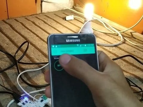
In this tutorial, we will demonstrate how to control control appliances instantly using the Blynk App only. When the button in Blynk App is touched, the Bynk App sends a signal to update the status of the virtual pin. If the button is turned ON, the app sends binary ‘1’, otherwise it sends binary ‘0’.
Requirements● 1x CW01 - Wi-Fi Core (ESP8266/ESP-12F)
● 1x IP01 - USB Programming Interface (FT232R)
● 1x OC03 - Relay Out (PCA9554A)
● 1x XC10 - 10-Pack xBus Connectors
● 1x 5V Power Supply
● 1x 5V Relay module. A 5V SRD-05DC-SL-C relay is used in this tutorial, but any 3.3V or 5V relay module can be used with changes in the code and connections.
● 1x Light bulb. An 11-W Fluorescent light bulb is used in this tutorial. However, any light bulb can be used.
● 1x Light bulb socket
● Blynk App
Step-by-Step1. Hardware Setup
2. Installing Arduino Libraries
3. Setting Up the Blynk App
4. Result
5. Summary
1. Hardware Setup1. Connect xChips CW01, OC03 and IP01 together using the XC10 xBus connectors. You may connect it as shown in the diagram below. Please see this guide on how to assemble xChips generally.
2. Connect VCC and GND of the Relay module to the Power Supply VCC and GND.
IMPORTANT NOTE: The Relay module pinout can be different depending on what relay module is used. Double check before connecting.
3. Connect IN/Signal pin of the Relay module to the GND or VCC (Depending on the trigger type) passing though xChip OC03 connectors. My Relay module is LOW-level trigger, therefore I have to connect to GND passing though xChip OC03 connectors.
4. Connect NO of the Relay module to the Neutral of the light bulb socket, and connect COM of the Relay module to Neutral of AC plug (See Relay module pinout image above).
5. Connect the Hot wire of the AC plug with the Hot wire of the light bulb socket.
2. Installing Arduino Libraries1. Install Arduino IDE 1.8.8.
2. Install these libraries into Arduino IDE:
NOTE: If you are not familiar with how to Install libraries, please refer to the link: Installing Arduino libraries
3. Setting Up the Blynk App1. Download the Blynk App.
2. Create your Blynk account and receive an Auth Token. For details see this guide.
3. Create Button Widget:
4. Select V5 pin:
In this project we have shown you how to make an immediate response Home Automation projects using XinaBox and Blynk App.


Comments