Years ago, I was late to a movie that a group of friends had invited me to go see. There were no parking spots outside of the theater and I was forced to park in the parking deck. When I pulled into the spot, I couldn't tell how close I was to the wall in front of me. There was a phantom distance between the front of my car and the end of the parking space and I wasn't sure how much room was left. Just before moving my car a few more inches into the spot I decided I would get out and check to see how much farther I could go. That's when I discovered I was less than an inch away from the wall. The damage would not have been severe however, I began thinking how often people like me have to park in a parking garage and are not always sure how close they truly are to the wall. That is what the IoT is intending to solve. This circuit is designed to have one part attached to the front of your car and the other part to be connected inside. The sensor on the front will transmit a wireless signal to the photon next to the driver's seat when the HR-SRO4 device gets within a selected distance. This will ensure that the car is not close enough to make contact with the wall however, it is far enough into the parking spot so that your vehicle will not be in danger of being hit by other passing cars. This gives a measure of safety to parking in tight places and gets rid of the phantom distance that we all dread.
Quick demonstration on how distance sensor works!
IFTTT is the program that we used to receive the events being sent from the main photon. This site allows the data to be recorded and posted in a google sheets page. This allows the information sent form the particle code to show up in real time in the program. It will update each time the sensor in the circuit is triggered and the LED lights up. Below is a live link of the amount of times the sensor is set off and recorded in the console. These data points can be erased each time you finish parking and get out of the car. The google sheets document is connected directly to the main photon so that each time the sensor gets close to the wall, another row of data will appear in the document. This will automatically be recorded on the graph as an event which will increase the bar graph.
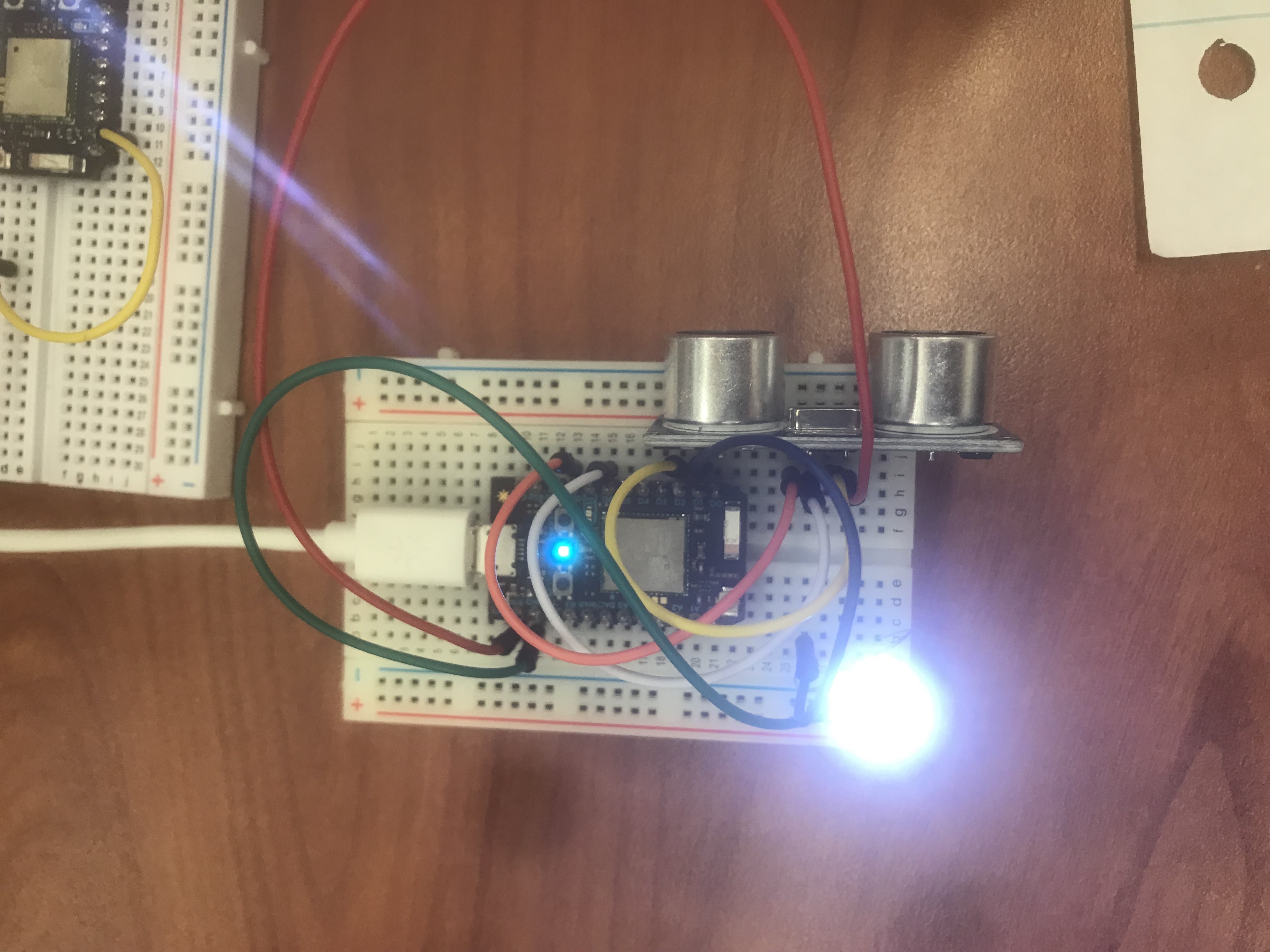
Top View of Photon with Sensor (Outside of Car). This view has a "wall" infront of it and shows how the led comes on.
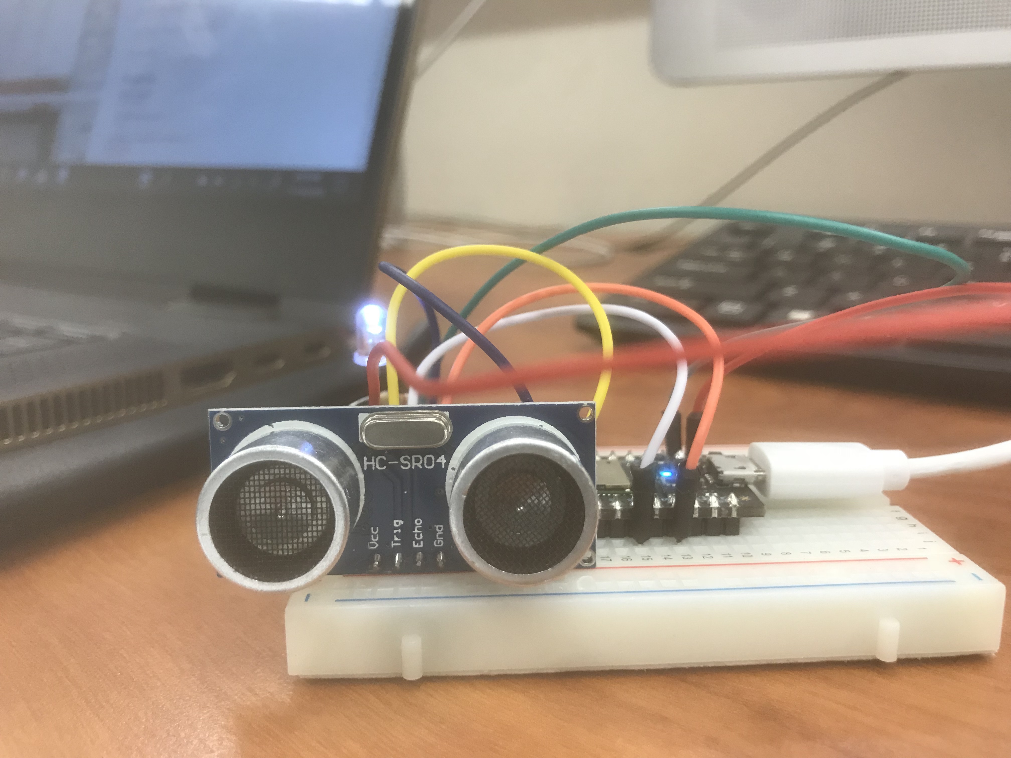
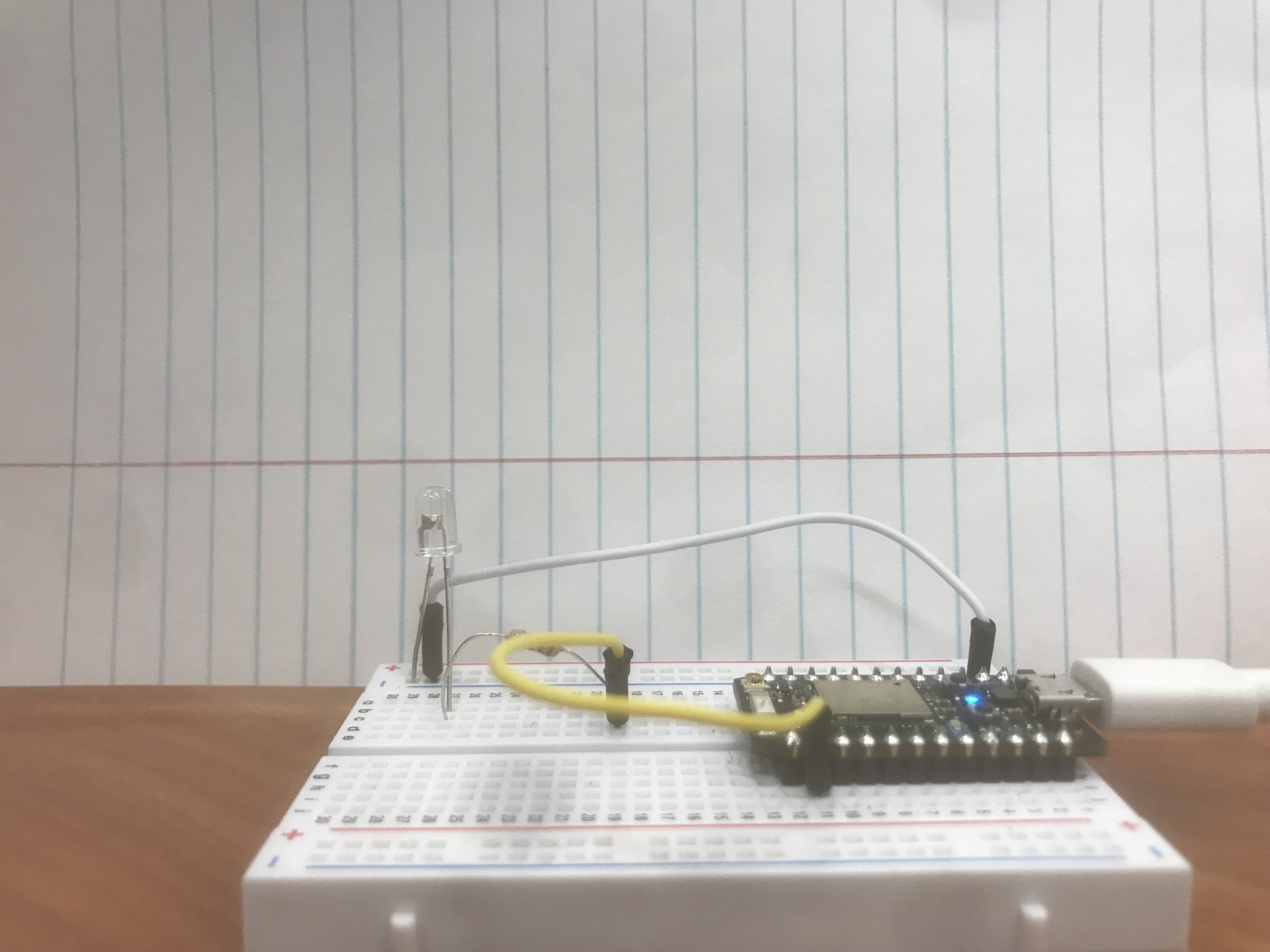
Side View of Photon with Sensor(Outside of Car)
Side View of Photon with Sensor (Outside of Car) This view has a "wall" infront of it and shows how the led comes on. Also shows HC-SR04 sensor with more detail.
Top View of Photon with Sensor (Outside of Car)
Top View of Photon with Sensor(Outside of Car) This view has the light off therefore no wall at close distance.
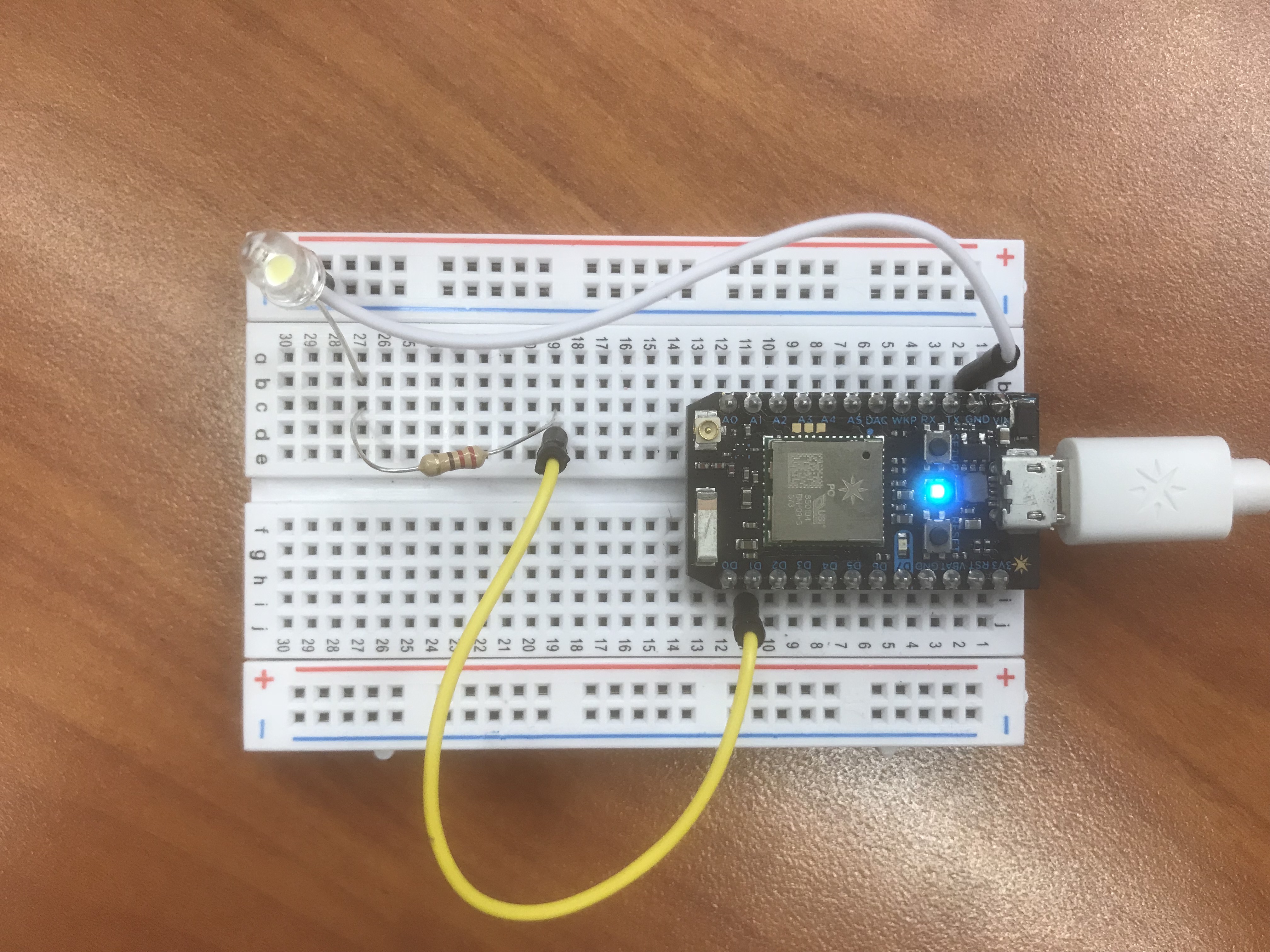
Top View of Photon that receives signal (Inside of Car)
Top View of Photon that receives signal (Inside of Car) Light is on therefore the main photon with sensor has a wall infront of it.
Side View of Photon that receives signal (Inside of Car)
Side View of Photon that receives signal (Inside of Car) Light is on therefore the main photon with sensor has a wall infront of it.
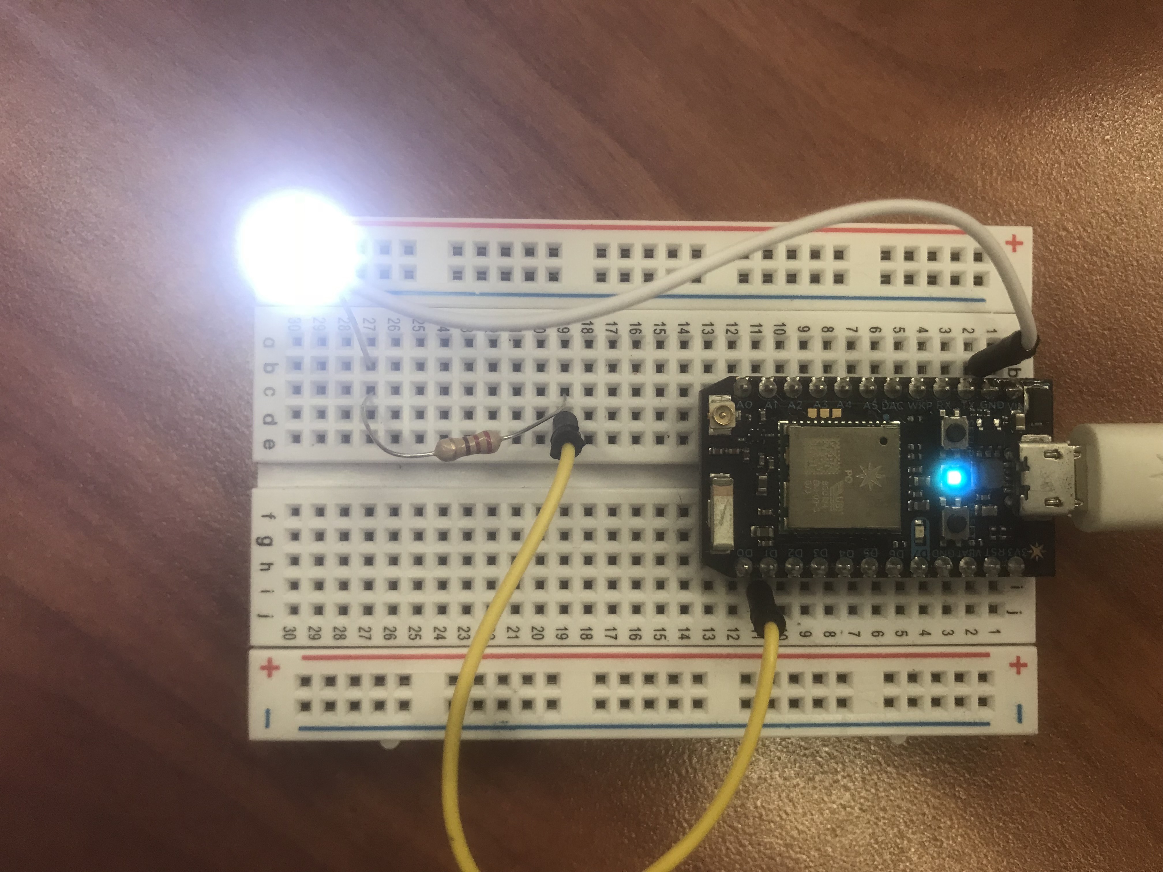
Top View of Photon that receives signal (Inside of Car)
Top View of Photon that receives signal (Inside of Car) Light is off therefore main photon with sensor has no wall infront.
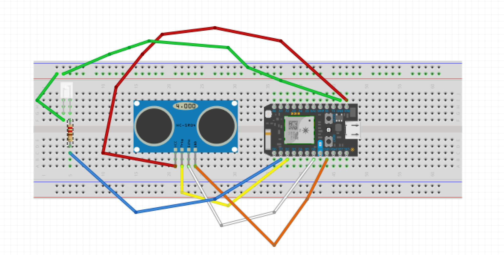
Schematic of Main Photon with HC-SR04 Sensor
Detailed wire schematic for main photon.
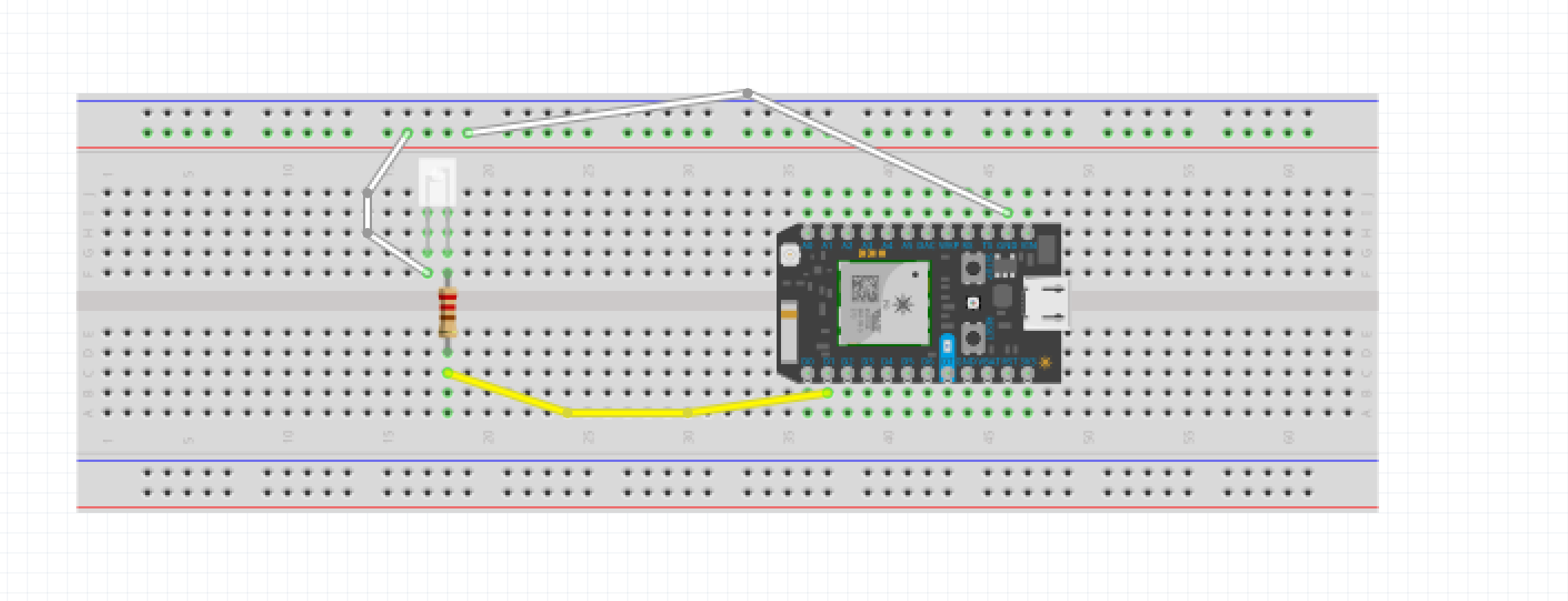
Schematic of Photon that Receives Signal.
Detailed schematic of photon that receives signal from main photon.
Code for Main Photon that has sensor Connected to it.
Arduino
This code works by selecting specific LEDs on the main photon to register the signals being sent through them. The loop has an "if statement" saying if the HR-SRO4 is within a certain distance, for example 35cm, the circuit will be triggered and light up the LED light on the main breadboard. The way the actual HR-SRO4 device works is it sends out signals and measures how long it takes for the signals to return to the device. This is usually recorded in microseconds. When the device is close enough to trigger a response, it records an event and publishes it to the console. This works by choosing a Particle.publish function and choosing what to label events that will appear in the console. A delay is added in order to give it time to reset and also for the other photon to have time to read the data that is already published.
unsigned long duration;unsigned long startMicros;long last;bool checking;void setup(){ pinMode(D7, OUTPUT); // LED on D7
pinMode(D1, OUTPUT); // Other LED connected from D1 through resistor to ground
// ultrasonic range finder Robotshop RB-lte-54
// GND pin goes to ground
pinMode(D6, INPUT); // echo pinMode(D2, OUTPUT); // Trig
// VCC pin goes to VIN on the photon
attachInterrupt(D6, rangeISR, FALLING); // interrupt on falling edge
}void loop(){if(checking==false&& millis() - last > 1000){ // once per second if not doing anything
checking= true; // set a flag so it doesn't get confused duration = 0; last = millis(); // get time now for timer digitalWrite(D2, HIGH); // activate trigger delayMicroseconds(10); digitalWrite(D2, LOW); // de-activate trigger startMicros = micros(); // get time now for start } if ( duration ) // it's been set by ISR
{if( duration > 2000){ // raw data from 200 to 16000 // where 2000raw= ~35cm, 4000raw= ~80cm
digitalWrite(D7, HIGH); // D7 Blue LED on if far
digitalWrite(D1, LOW); // Other LED off
}else{ digitalWrite(D7, LOW); // D7 Blue LED off
digitalWrite(D1, HIGH);// Other LED on if Close
Particle.publish("Wall828", "Close");}checking= false; // reset the flag to signal a start
duration=0; // reset this as well
delay(10); // even circuits need a break}}void rangeISR(){duration= micros() - startMicros; // sets duration to current time - start time}
Photon Receiver Code
Arduino
This code was used for the second photon in the circuit. This photon was responsible for signaling when the HR-SRO4 sensor was too close an object. This was achieved by subscribing this particle to the main photon and the console that contains all the events that were being recorded. The same LED instructions from the main code were also used to set off the light that was attached to the secondary photon. A delay was added to this device as well however, unlike the the first code, this delay only lasts for two seconds. After the delay, which is about two seconds, the power to the light is switched off. That allows the LED light to come on, get recognized and then reset incase it is needed again.
unsigned long duration;unsigned long startMicros;long last;bool checking;void setup(){ Particle.subscribe("Wall828", myHandler, "300025000d51353532343635"); pinMode(D7, OUTPUT); // LED on D7
pinMode(D1, OUTPUT); // Other LED connected from D1 through resistor to ground
// ultrasonic range finder Robotshop RB-lte-54
// GND pin goes to ground
pinMode(D6, INPUT); // echo pinMode(D2, OUTPUT); // Trig
// VCC pin goes to VIN on the photon
attachInterrupt(D6, rangeISR, FALLING); // interrupt on falling edge
}void myHandler(const char *event, const char *data){ digitalWrite(D1, HIGH); // if(checking==false&& millis() - last > 1000){ // once per second if not doing anything
// checking= true; // set a flag so it doesn't get confused // duration = 0; // last = millis(); // get time now for timer // digitalWrite(D2, HIGH); // activate trigger // delayMicroseconds(10); // digitalWrite(D2, LOW); // de-activate trigger // startMicros = micros(); // get time now for start // if ( duration ) // it's been set by ISR
//{ // if( duration > 2000){ // raw data from 200 to 16000 // where 2000raw= ~35cm, 4000raw= ~80cm
// digitalWrite(D7, HIGH); // D7 Blue LED on if far
// digitalWrite(D1, LOW); // Other LED off
// }else{ // digitalWrite(D7, LOW); // D7 Blue LED off
// digitalWrite(D1, HIGH); // Other LED on if Close
// } // checking= false; // reset the flag to signal a start
// duration=0; // reset this as well
delay(2000); digitalWrite(D1, LOW);// even circuits need a break}void rangeISR(){ // duration= micros() - startMicros; // sets duration to current time - start time}


Comments