


Hardware components | ||||||
 |
| × | 2 | |||
 |
| × | 3 | |||
 |
| × | 2 | |||
 |
| × | 2 | |||
 |
| × | 3 | |||
 |
| × | 2 | |||
 |
| × | 1 | |||
 |
| × | 3 | |||
| × | 21 | ||||
| × | 2 | ||||
Software apps and online services | ||||||
 |
| |||||
| ||||||
 |
| |||||
 |
| |||||
On the surface, temperature sensors do not sound awesome. Just the word temperature makes you think about being sick, or staring at one of those big sunflower thermometers on your grandparents back porch that is either 50 degrees off or it is the hottest day on earth...ever. (It may have just been grandmas lack of precision painting the lines). Anyway, temperature sensors still do not sound interesting, or very useful. This is where IOT comes in. What would you say if we told you that you could monitor the temperature inside the trunk of your Buick while you ran into the grocery store for milk, if for whatever reason you needed to do that? That might be extreme, but we came up with some great reasons to remotely monitor temperature. Here is a few…
- Monitor the temperature of individual rooms in your house simultaneously instead of relying on one central thermostat that leaves the extremities of your house freezing in the winter.
- Soup too hot? Just place the thermistor in the bowl and wait until a fancy LED light blinks to let you know it is just the right temperature.
- Concerned that the temperature gradient of your climate controlled greenhouse is out of limits? Remotely monitor and log temperature data over the course of a few weeks, use it to identify shortfalls, and show your friends!
Seriously, temperature sensors can provide endless fun and endless analyzable data! With so many possibilities, we thought we should provide the world with an easy to use, data logging, two way communicating, temperature sensing system so others can have as much fun as us!
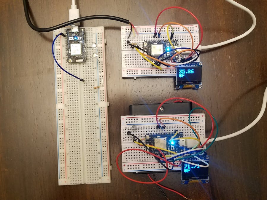
Our temperature sensor system consists of three Particle Photons, two 0.96” OLED screens (they came with the Makers Kit), three half size solderless breadboards, two white LED lights, two temperature sensors, a bunch of wires, and a few resistor (the schematics and pictures explain it better).
Two of the Photon setups are identical, with a Photon connected to the OLED and a temperature sensor. The Photon itself receives temperature data from the temperature sensor and displays it on the OLED screen every 25 seconds. The temperature sensor units publish the temperature data to the cloud in a string, with Photon number three (the different one) subscribing to each of the sensor units’ events. When the sensor units publish data simultaneously, both white LED lights on the third photon and the blue D7 LEDs on each sensing unit blink, periodically letting the user know that the entire system is communicating. The temperature data is published to a Google Doc, controlled by If This Than That (IFTTT), writing a new line for each temperature event with a time stamp.
We needed to put our bulletproof temperature sensing system to the test, so we decided to do what anyone in our position would do...we set one temperature sensor up in the refrigerator in the garage, and another on the back porch to see if it is that time of the year again, you know, when you can leave a 12 pack of (the your beverage of choice) by the back door instead of walking all the way to fridge!
Below is some of the groundbreaking data we logged!
Figure 1 above is a chart depicting the temperatures measured by the two separate Photon temperature sensors. The blue line is the temperature of our refrigerator (we like to keep it frosty!), and the orange line is the outdoor temperature. As you can see, it is not cold enough to shut the refrigerator down for the season.
Figure 2 above is the differential between the outdoor and refrigerator temperature. The variance in temperature differential early in our experiment does not seem to represent the actual temperature accurately. According to figure 1, the refrigerator temperature held steady and the outdoor temperature varied about 4 degrees in the beginning. It is hard to justify this pattern based on normal outdoor heating and cooling, leading us to believe there was some kind of outside interference between 1500 and 1600 (you shouldn't mess with other peoples temperature sensors).
The temperature sensors are apparently not as bulletproof as we thought, yet they sure did the job. The (beverage of your choice) refrigerator is still in service, we have a ton of data to scrub through and we are on to our next experiment.
Here are the links to the sheets of the groundbreaking data! This was done using two IFTTT applets that recognized published temperature values from each temp sensor through Particle, then added a new line to a Google Sheets spreadsheet with a timestamp.
Below are images showing both temp sensors that could be used, and the specific type of OLED screen that was used. All of these components can be found in a particle maker kit.
Three Prong Temp Sensor:
Sealed Temp Sensor:
OLED Screen:
Main Photon Schematic
The two temperature sensor photons publish their data to the particle cloud. This main photon is subscribed to both photons with specific event name codes. When this main photon sees that temp sensor 1 or 2 has successfully uploaded temp data to the cloud, it blinks the corresponding LED. This indicates that both the temp sensor itself is functioning properly, and that this main photon is successfully subscribed to the individual temp sensors.
When this main photon has both of its LED indicators on at the same time, it sends a signal to the temp sensors to blink their D7 photon LEDs. This allows for someone on the temp sensor end of the system to see that the entire system is functioning properly. If the D7 on a temp sensor does not blink, then this tells the user that the system has at least one temp sensor not functioning properly. This is also shown by the main photon's white LED indicators blinking for the specific temp sensors. If one of the white LEDs on this photon is not blinking periodically, then the corresponding temp sensor is not functioning properly.

Temp Sensor 1 and 2 Schematic
To setup these photons, individually, one requires an OLED screen from the particle maker kit, a 4.7 kΩ resistor, either a small three prong temp sensor or a sealed temp sensor (both are also in the maker kit), and many jumper wires.
The differences between the temp sensors comes in the code. They publish their own distinct data ID to the particle cloud, temp1sensor123987 and temp2sensor987123 for temp sensors 1 and 2 respectively. These must be unique for each sensor because in order to subscribe to the data correctly, it helps for the data to have its own unique ID, so as to avoid any unnecessary data overlapping with other people who may be doing similar projects.


Comments