Android guided vehicle is a project I have done for Flex Your Mind with Kinetis FlexIO contest. I made used of the NXP Freedom K82F Development Board which I was awarded and I've developed an Android app which sends the destination and direction to the Freedom Board (vehicle) via Bluetooth.
What is AGV (Automatic Guided Vehicle)It is a mobile robot that follows markers or wires in the floor, or uses vision, magnets, or lasers for navigation. They are most often used in industrial applications to move materials around a manufacturing facility or warehouse. Application of the automatic guided vehicle has broadened during the late 20th century. the navigation is based on wiring, guide tapes, laser target navigation, vison guidance, nature targeting etc and the steering control, traffic control, path decisions are made using various complex algorithms and as a result the complexity and cost of the AGV is increased.
Getting Started to FRDM-K82F and Kinetis SDK (KSDK)- Download the Kinetis Design studio IDE and install it
- Download the driver for Windows and Install it by plugging in the board. Link: http://developer.mbed.org/media/downloads/drivers/mbedWinSerial_16466.exe
- Go to http://kex.nxp.com/en/welcome sign in, choose your board, build and download the SDK
- We have to download a binary file from https://www.segger.com/opensda.html and load it to the FRDM K82F Board
Using Demo Apps- Browse to the SDK 'examples' folder of your SDK installation and select your board, the FRDM-K82F (<SDK_Install_Directory>/examples/frdmk82f).
- Import any of the demo_app by using kinetis design studio (KDS).
- Then by clicking the 'debug' icon in the bar enter into the debug configuration
- Click the Debug button, it will upload the code to the FRDM board
- It shows a prompt message and you are done .
IntroductionMy motive is to make a small Android Guided Vehicle which performs the similar tasks of an AGV but the process involved in path decision, traffic control, controlling is simpler and cost required in building the vehicle is less and when it comes to the programming and electronic hardware requirement it's much simpler and reasonable accuracy can be obtained.
Black lines are painted as a replacement for magnetic tapes, reflective tapes, lasers, wires etc.. We can consider this Android Guided Vehicle as an intelligent line follower which also receives commands from the user or controller
The AGV's available in market are very expensive and it can be used efficiently only in big industries and it also requires proper installation of navigation systems. But our Android guided vehicle is less expensive when compared and can be used in smaller industries and in places where less transport of materials are involved
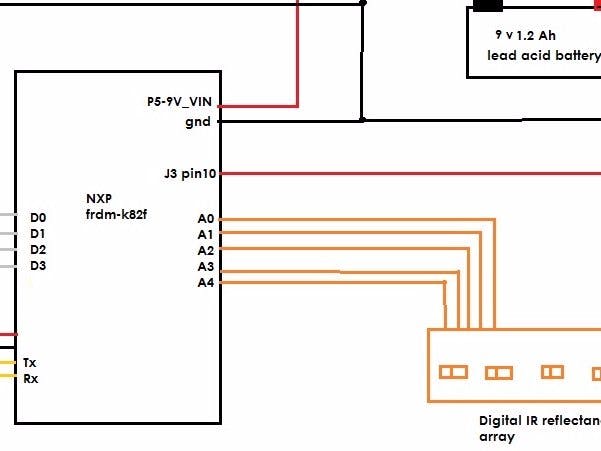
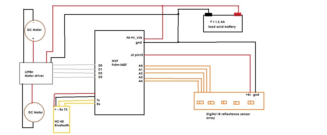
Role of NXP Freedom K82F Development Board- The Freedom Board controls Right, Left, Forward and Backward movement of the car by sending signals to the L298 motor driver.
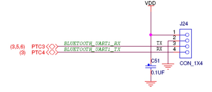
- I’ve added a Bluetooth module (HC-05) which is connected to the Freedom Board via UART interface, this HC-05 module receives data from the smartphone app.
- IR transceiver pairs are connected to GPIO/Digital pins of the board so that the black line drawn on the ground can be sensed
The Android APPThe path for moving the materials is selected by the operator using the android app ie. the starting and ending points are sent to the vehicle as a pair of strings via bluetooth and each point is represented using a string as shown in the blocks
App Inventor is a cloud-based tool, which means you can build apps right in your web browser.
http://appinventor.mit.edu/explore/get-started.html
I've also uploaded the .aia file along with the .apk for this android app
Application- Repetitive movement of materials over a distance
- Regular delivery of stable loads
- Finished product handling


_ztBMuBhMHo.jpg?auto=compress%2Cformat&w=48&h=48&fit=fill&bg=ffffff)


_3u05Tpwasz.png?auto=compress%2Cformat&w=40&h=40&fit=fillmax&bg=fff&dpr=2)


Comments