IntroductionThe Lehman College Exercise Science Department was conducting studies around weight training. There were inconsistencies in range of motion for repetitions, which could significantly influence the data. I had 2 weeks to come up with a concept and create a finished product with the following criteria:
- Adjustable Distance
- Not permanently fixed to machines
- Tripod Compatible
- Battery Powered
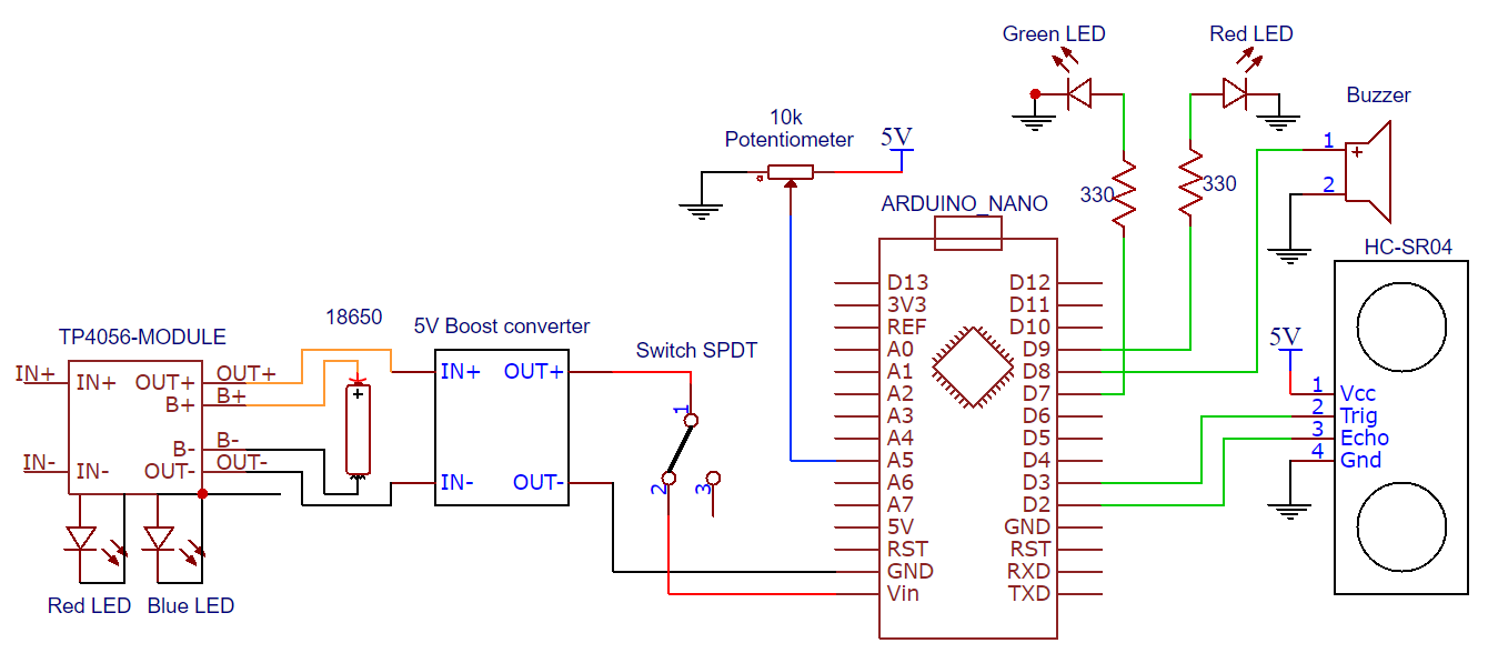
VideoPartsI used an Arduino Nano with an HC-SE04 ultrasonic sensor to detect distance. With a 30° field of view, I had leeway on positioning under weights.
A LiPo battery with a 5V boot converter powers the Arduino. The TP4056 charges the battery.
The potentiometer adjusts trigger distance, while the buzzer provides audible feedback when an object crosses the trigger distance.
Additional red & blue LED, and (4) 10mm M3 bolts required
The NewPing library helps interface with the ultrasonic sensor. 3 beeps occur on power up to indicate that the boot was successful. Position data is constantly compared to the threshold set by the potentiometer. When the threshold is crossed, the buzzer is turned on.
3D PrintingAll files have been uploaded to thingiverse and at the bottom of this page.
1 / 2 • Red = manual supports
Print times will vary, but my print times were as follows:
- Top Piece: 2 hours 40 minutes
- Bottom Piece: 2 hours 20 minutes
- Knob: 20 minutes
AssemblyWarning: Spaghetti, hot glue, soldered batteries ahead. Time was very limited.
Soldering 18650 cells is bad practice. Spot weld if possible.
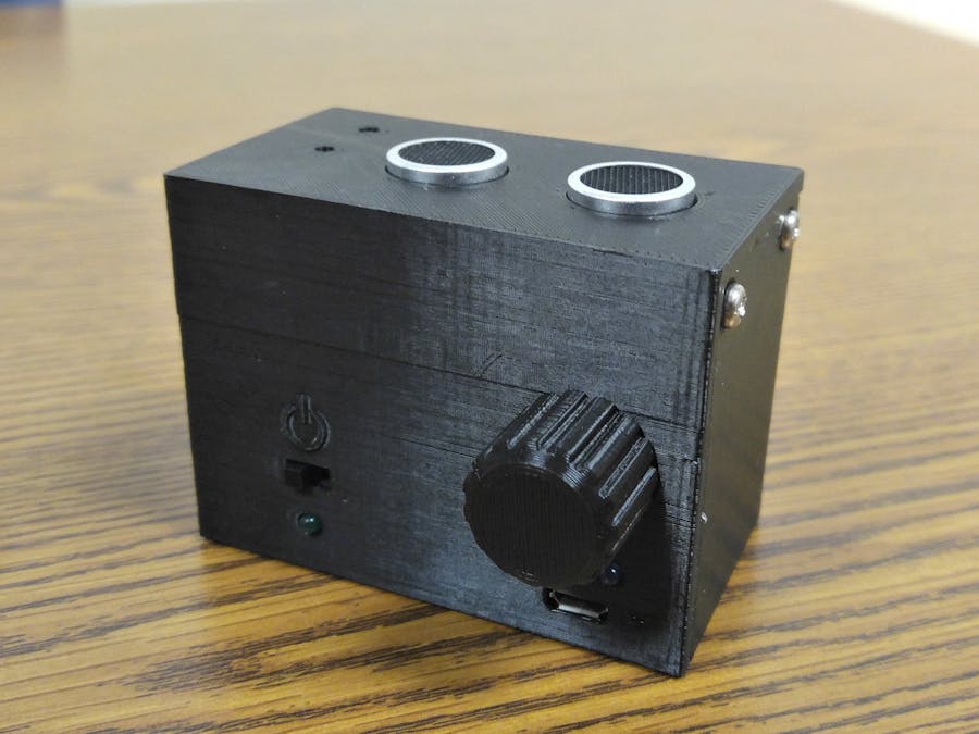
Parts wired and fitted into enclosure
Final assembly:
Gave it to the professor just in time!


Comments