

Hardware components | ||||||
 |
| × | 1 | |||
| × | 1 | ||||
How to control an I2C DAC with the IOT2020. The program is based on Siemens' SIMATIC IOT2000 I²C example LED and Peter Oakes' Arduino article.
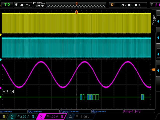
SCK SDA and analog output
The example is simple. A buffer holds 256 samples of a sinus signal. Our code loops trough that buffer and sets the DAC to each of the values. Forever. The result is a sinus signal on the output of the DAC. The DAC talks I2C. So each of the buffer values is sent to the DAC8571 via that protocol.
Code being debugged with Eclipse NEON
#include
#include "mraa.hpp"
using namespace std;
uint16_t Sin_tab[256] = { 32768, 33572, 34376, 35178, 35980, 36779, 37576,
  38370, 39161, 39947, 40730, 41507, 42280, 43046, 43807, 44561, 45307,
  46047, 46778, 47500, 48214, 48919, 49614, 50298, 50972, 51636, 52287,
  52927, 53555, 54171, 54773, 55362, 55938, 56499, 57047, 57579, 58097,
  58600, 59087, 59558, 60013, 60451, 60873, 61278, 61666, 62036, 62389,
  62724, 63041, 63339, 63620, 63881, 64124, 64348, 64553, 64739, 64905,
  65053, 65180, 65289, 65377, 65446, 65496, 65525, 65535, 65525, 65496,
  65446, 65377, 65289, 65180, 65053, 64905, 64739, 64553, 64348, 64124,
  63881, 63620, 63339, 63041, 62724, 62389, 62036, 61666, 61278, 60873,
  60451, 60013, 59558, 59087, 58600, 58097, 57579, 57047, 56499, 55938,
  55362, 54773, 54171, 53555, 52927, 52287, 51636, 50972, 50298, 49614,
  48919, 48214, 47500, 46778, 46047, 45307, 44561, 43807, 43046, 42280,
  41507, 40730, 39947, 39161, 38370, 37576, 36779, 35980, 35178, 34376,
  33572, 32768, 31964, 31160, 30358, 29556, 28757, 27960, 27166, 26375,
  25589, 24806, 24029, 23256, 22490, 21729, 20975, 20229, 19489, 18758,
  18036, 17322, 16617, 15922, 15238, 14564, 13900, 13249, 12609, 11981,
  11365, 10763, 10174, 9598, 9037, 8489, 7957, 7439, 6936, 6449, 5978,
  5523, 5085, 4663, 4258, 3870, 3500, 3147, 2812, 2495, 2197, 1916, 1655,
  1412, 1188, 983, 797, 631, 483, 356, 247, 159, 90, 40, 11, 1, 11, 40,
  90, 159, 247, 356, 483, 631, 797, 983, 1188, 1412, 1655, 1916, 2197,
  2495, 2812, 3147, 3500, 3870, 4258, 4663, 5085, 5523, 5978, 6449, 6936,
  7439, 7957, 8489, 9037, 9598, 10174, 10763, 11365, 11981, 12609, 13249,
  13900, 14564, 15238, 15922, 16617, 17322, 18036, 18758, 19489, 20229,
  20975, 21729, 22490, 23256, 24029, 24806, 25589, 26375, 27166, 27960,
  28757, 29556, 30358, 31160, 31964 };
int main() {
  uint8_t txBuffer[3];
  mraa::I2c* i2c;
  int i;
  i2c = new mraa::I2c(0);
  i2c->address(0x4C); //set address of DAC
  txBuffer[0] = 0x10; // set value direct
 while (1) {
    for (i = 0; i < 256; i++) {
       txBuffer[1] = Sin_tab[i] >> 8;
      txBuffer[2] = Sin_tab[i];
      i2c->write(txBuffer, 3);
    }
  }
  return 0;
}
- 0x4C is the I2C address of the DAC.
- buffer[0] contains the value 0x10: adapt output to payload immediately
- buffer[1] contains the high bits of the 16 bit value
- buffer[2] the low bits.
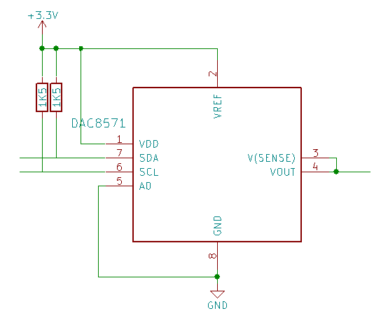
You need two I2C pull-up resistors (1K5 or whatever you have) and the DAC8571.
- 3V3 to X13.P4
- GND to X13.P6
- SDA to X10.P9
- SCL to X10.P10
Arduino Header allocations
Attach one of your oscilloscope probes to the DAC output, it's alligator clip to GND. You can also hook up a protocol analyser and check the traffic.
Happy I²C-ing!


Comments