


This project will cover the MAX32660 microcontroller's setup and showcase one project example. The controller itself offers a wide range of configurations, so it is a great candidate for any low-power, wearable projects.
The initial project design was aimed at a wearable human body temperature sensor that would display the user's temperature onto an electronic ink display. Battery life has always been an obstacle when it comes to wearable technology, so this project aims at lowering the overall power consumption of each individual component. This post will focus on the initial project setup and proof of concept for the project design. Part 2 goes through the power saving techniques and results.
MaterialsAs far as materials go, there are only three components required for this build.
MAX32660-EVSYS (1) --- Purchase Here
MAX30205-EVSYS (1) --- Purchase Here
SSD1608 - 1.54" Electronic Ink Display (E-ink) (1) --- Purchase Here
Jumper Wires (20 or so)
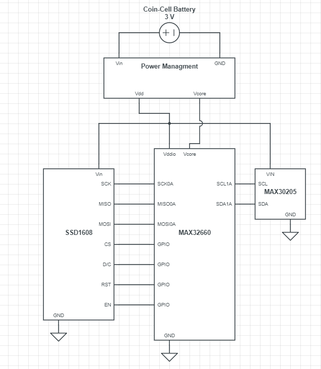
Pin ConfigurationI have attached an image of the MAX32660-EVSYS pin configuration. Notice the position of the onboard button, and use it as a reference for wiring your components. Any changes in the pins used on the MAX32660 will require minor adjustments in the code.
MAX32660-EVSYS -> ElectronicInkDisplay
VDDIO -> VIN
GND -> GND
P0_6 (SCK) -> SCK
P0_5 (MOSI) -> MOSI
P0_4 (MISO) -> MISO
P0_10 (GPIO) -> ECS
P0_8 (GPIO) -> D/C
P0_9 (GPIO) -> RST
P0_11 (GPIO) -> EN
MAX32660-EVSYS -> MAX30205EVSYS
The temperature sensor uses I2C communication protocol, so it only requires 2 wires for data transfer. The E-ink display uses SPI communication protocol, so it requires extra connections. The E-ink display has clear labels on each pin, so make sure to follow them carefully. When wiring up the MAX30205, make sure to use the white circle at the top of the pins as a guide.
The MAX30205-EVSYS does not come with pre-installed pull-up resistors. If you leave the ribbon wire attached, the current measured will be higher than it should be. This can be attributed to the fact that your microcontroller will also be powering the EV-Kit, not just the sensor itself. In order to fix this issue, you should remove the ribbon wire and solder two pull up resistors to the R1 and R2 spaces. I choose 5 kΩ (0402) pull-up resistors, but any values around that should work. (See R1 and R2 locations below). If you would rather not solder the resistors, leave the ribbon attached and the sensor will use the EV-Kit resistors -- Just be warned that your current consumption will be much higher.
VDDIO -> VIN
GND -> GND
P0_2 (SCL) -> SCL
P0_3 (SDA) -> SDA
Once the components are properly wired, it is time to upload the sample code. In order to use Maxim Integrated microcontrollers effectively, we need to make sure we are using the Maxim toolchain within eclipse. There is a great video on installing the toolchain and using eclipse here: How to Set Up theMAX32630/MAX32631 Evaluation Kits in Eclipse. (1:10 - 3:50) Instead of preparing a folder with MAX32630 examples, make sure to choose MAX32660. For more information on the Maxim ARM toolchain, open the "README" file inside your toolchain install folder.
Once you are in eclipse, go to file->New->Maxim Microcontrollers. This will open up a project initialization page. Name your project and select next.
For the next prompt enter:
Chip Type: MAX32660
Board Type: EVKit_V1
Example Type: Hello_World
Adapter Type: CMSIS-DAP
After this is complete, hit finish and you should see your new project appear in the left-hand window. Open the main.c file by double clicking, and make sure that the toolchain was setup correctly. Try to build the project, and confirm that the new project was created properly. If you get errors saying, “Unresolved Inclusion, ” the toolchain’s inclusion files need to be re-linked. Instructions on how to re-link these files can be found here: https://maximsupport.microsoftcrmportals.com/en-us/knowledgebase/article/KA-02684. You may still have some underlined inclusions that appear to be missing. After re-linking the inclusion files, just close and reopen the program and they should go away.
Once you are able to build the project, you are ready to implement the code provided. You can find my code libraries at the bottom of this article. Download all of the files, and copy them into the new project that you made. In this example, I named my project "Library_Trial." Also, make sure that you only have one main.c file. You can delete the old main.c that was generated when you first created the project. After you update the main.c, your file explorer window should show:
Now we have to edit the Makefile in order to compile the added.c files. By default, the Makefile will only compile the main.c file and any additional header files in your project when building. We want to make sure that it also compiles the additional.c files, so open it by double clicking, and scroll down to line 68. You should see:
SRCS = main.c
We want to specify the additional files here, and add a '+' before the equal sign to indicate multiple compilations. Make sure to spell the file names exactly as they appear in the project folder so that the compiler can find them (including capitalization). The modification should look like this:
Once the Makefile has been updated and saved, you need to clean the project and re-build. Just right click the project name in the file explorer, and you should see options for "Clean Project" and "Build Project." The build time could take anywhere between one and five minutes, which is likely due to the graphics content of the project. The first build tends to take slightly longer than the following ones.
Running the ProgramAfter the compiler has finished building, enter debugger mode by selecting the bug icon at the top toolbar.
Make sure that your MAX32660 is plugged into your computer via the provided micro-USB. Once the debugger has uploaded the program, select the green arrow at the top of your screen.
If you are prompted to select a debugging format, choose the debugging settings under the "GBD OpenOCD Debugging" with the project name you wish to debug.
Once the project has been uploaded, select the green arrow at the top of your screen to begin the program.
You will see the Maxim Integrated logo appear on the e-ink display. After 5 seconds, the screen should change and display the current temperature. The screen will continually update every 10 seconds. If the on-board button is pressed once, the device will enter into deep-sleep mode between measurements. There is more information on this feature in part 2, so I would recommend giving it a read. The device will appear to function the same way, but you may get error messages in the Eclipse debugger menu saying that the microcontroller was disconnected. The communications lines are shut-off, so the debugger believes that the microcontroller is offline. In order to get back to the microcontroller back into active mode, you have to press the button during a screen transition. It must be pressed during a transition, or else the micro will not recognize it and will return to deep-sleep mode. You can see a sample transition in the video below. The transition should only last a couple seconds, so you have to be quick.
If the device gets stuck in deep-sleep mode, and cannot transition it back into active mode, then you may need to erase the microcontroller's data. This can be caused by improper programming, where code was uploaded without a proper wake-up mechanism. This example uses the RTC, but you can also setup a GPIO enable. You can wipe the memory by following this quick tutorial.
The final product should look something like this (Note that the time between readings was decreased to 2 seconds in order to speed up the video).
ModificationWithin the Display.h file and its respective.c file, you will find the basic screen-write functions used in this project. These functions utilize the DispLUT.h file which holds the screen data. Each bit held within the look-up table is used to change one bit (Hence, 1 byte can manipulate 8 pixels, and 5000 bytes are required to store one entire screen). In order to create new bitmaps for the look-up table, you will need to download Gimp, which can be found at https://www.gimp.org/.
Once downloaded, open the program and select: File -> New. One the next screen, make sure to input 200 x 200 pixels.
Download a copy of the image you would like to display. Keep in mind that the screen is monochrome, so any photo with a lot of colors or shading may not display as well. For this example, I will use a black and white image of the New York Yankees logo. Once the image is downloaded, drag and drop it from your downloads folder into the new Gimp project.
Now make sure that the image layer is selected on the bottom right hand corner of your window, and right click the image in the middle of your screen. Go to Layer-> Scale Layer
Set the new scaled image size to be 200 x 200. If you want to retain the original images proportions, only change the larger dimension size to 200, and the other dimension will automatically update. This will prevent image distortion from stretching or compressing the image.
Now that your image is properly scaled, you are ready to export. Go to file -> Export As... At the bottom of the window, click on "Select File Type (By Extension)" and scroll through the list until you find "X Bitmap image." Name the file and hit Export. Another window will pop-up, and just leave the default settings and hit "Export" again.
Now find the exported file, and open it with your preferred text editor. WordPad works fine here. Select the entire file content with CTRL + A and copy it to your clipboard. Open up Eclipse and go into your project's SSD1608_Display_LUT.h file. Find the uint8_t array called "logo" and paste the exported file contents inside the curly brackets. Make sure to delete any additional brackets or declarations within the pasted file.
Go to your main.c, and paste in the new code for your main function:
int main(void)
{
    //Initialize SPI
    SPIinit();
   //Initialize GPIO Pins
   pinInit ();
   //Display new Screen in logo array
    StartScreen();

   return 0;
}
Make sure to save all of the files, and clean the project. Build the project and enter the debugger. The loaded image should appear on your display.
Remember to visit part 2, which goes over the power saving techniques and measurements.


Comments