

Hardware components | ||||||
 |
| × | 1 | |||
| × | 1 | ||||
| × | 1 | ||||
| × | 1 | ||||
| × | 1 | ||||
| × | 1 | ||||
Software apps and online services | ||||||
 |
| |||||
 |
| |||||
In several systems that monitor the temperature, it is of fundamental importance to check the operation of the temperature sensor, before starting the operation of reading the data.
It is important because, in the case of sensor failures, the temperature monitoring device will not be able to detect variations in the system temperature.
Therefore, in the case of system temperature failure, the device will not be able to detect the variation and accidents and malfunctions may occur.
So, as a way to avoid these types of accidents, we will develop a system capable of verifying the operation of the DS18B20 temperature sensor and indicate when it is in normal operation in the system and inform the LCD 16x2.
Development of the SystemSeveral temperature monitoring devices use the DS18B20 sensor because it is a digital sensor with great accuracy in temperature measurement.
And due to its great applicability, we must ensure the safety of the system equipment by monitoring its operation.
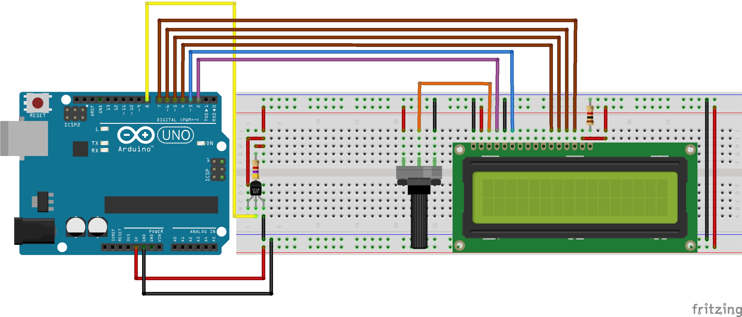
In this way, we present an electronic schematic of a circuit with Arduino, to present the temperature of the process and verify the operation of the sensor.
The program system will be responsible for reading the temperature and displaying the value on the 16 x 2 LCD. And with each finalization of reading and display of the values on the 16 x 2 LCD, the system will perform a functional check of the sensor.
All of this is done based on the programming logic presented following.
System Programming LogicBefore of entering in the void setup function, we declare all libraries used in our Project, we define the digital pin used to connect DS18B20 Sensor and we inform the digital pin used to connect the 16 x 2 LCD.
#include <OneWire.h> //OneWire Library for DS18B20 Sensor
#include <DallasTemperature.h> //Library with all function of DS18B20 Sensor
#include <LiquidCrystal.h> //Library for LCD 16 x 2

#define ONE_WIRE_BUS 8 //Digital Pin to connect the DS18B20 Sensor

OneWire oneWire(ONE_WIRE_BUS);
DallasTemperature sensors(&oneWire);

DeviceAddress sensor1;

const int rs = 2, en = 3, d4 = 4, d5 = 5, d6 = 6, d7 = 7;
LiquidCrystal lcd(rs, en, d4, d5, d6, d7);

bool ControlAccess = 0;
After this, we will enter the void setup function. At this step, the baud rate was defined for 9600 and the LCD and DS18B20 Sensor was initialized.
After config, the devices occurred o the test process of the sensor. The following command is responsible to get how many sensors are connected on the bus. As in our Project there is only one sensor, is expected that the system detects one sensor.
But, if occur anyone problem with the sensor, it will not be returned value of the address of the sensor. In the case, the system will inform that occur some problem with the sensor in the LCD.
Case your sensor works normally, the system will enter the void loop function and will start the reading process of the temperature and present in the LCD 16 x 2, as is present below.
void setup(void)
{
 Serial.begin(9600);
 sensors.begin();
 lcd.begin(16, 2);
 // Localiza e mostra enderecos dos sensores
 Serial.println("Localizing DS18B20 sensor...");
 Serial.print("Sensor Localization successfully!");
 Serial.print(sensors.getDeviceCount(), DEC);
 Serial.println(" Sensor");

     do
     {
       if (!sensors.getAddress(sensor1, 0))
       {
           if(ControlAccess == 0)
           {
             lcd.clear();
             lcd.setCursor(1,0);
             lcd.print("Sensor do not");
             lcd.setCursor(5,1);
             lcd.print("find!");
             ControlAccess = 1;
           }
         Serial.println("Sensor not found!");
       }
     }while(!sensors.getAddress(sensor1, 0));
         ControlAccess = 0;
}
After this process, the system will verify if the sensor is working normally. Case occur anyone problem, will present the “Sensor not found!” message.
And it will remain in the loop until the sensor problem is solved, a new sensor is installed or the user must restart the system.
But, case the sensor is working normally, the system enters on the void loop and will be read the temperature value, showing in the LCD 16x2 and test the sensor again, as is presented in the code below.
void loop()
{

 sensors.requestTemperatures();  //Request temperature
 float tempC = sensors.getTempC(sensor1); //Get temperature value
 //Show temperature value in the Display LCD 16x2
 lcd.clear();

 lcd.setCursor(2,0);
 lcd.print("Temperature");

 lcd.setCursor(4,1);
 lcd.print(tempC);
 lcd.write(223);
 lcd.print("C");

 delay(3000);
 //Verify the working of the DS18B20 Sensor
 Serial.print("Sensor Localization with Successfully");
 Serial.print(sensors.getDeviceCount(), DEC);
 Serial.println(" Sensor");
     do
     {
       if (!sensors.getAddress(sensor1, 0))
       {
           if(ControlAccess == 0)
           {
             lcd.clear();
             lcd.setCursor(3,0);
             lcd.print("Sensor not");
             lcd.setCursor(5,1);
             lcd.print("found!");
             ControlAccess = 1;
           }
         Serial.println("Sensor not found!");
       }
     }while(!sensors.getAddress(sensor1, 0));
         ControlAccess = 0;
}
For you to understand the operation, we present the results of the project with the actual images of the circuit mounted on the protoboard.
ResultsAccording to the diagram shown in Figure 1, note that when the sensor is connected and operating normally, the system reads and displays the temperature value, as in Figure 2.
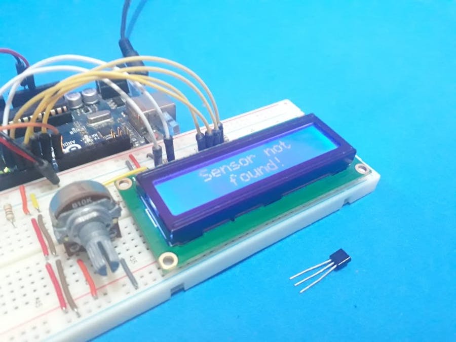
Now, when occurring anyone problem in the sensor circuit, the system will present the message "Sensor not found!". In Figure 3, the sensor was removed from the circuit and was presented the message.
Therefore, the system is very utility when is a need to detect a fault in the sensor in various projects which can occur heating problems.
AcknowledgmentThanks to the PCBWay for support the our YouTube Channel and produce and assembly PCBs with better quality.
The Silícios Lab thanks UTSOURCE to offer the electronic components.


Comments