Electronics Champ
Published © GPL3+

How to Connect nRF24L01 and MPU6050 for Gesture Control

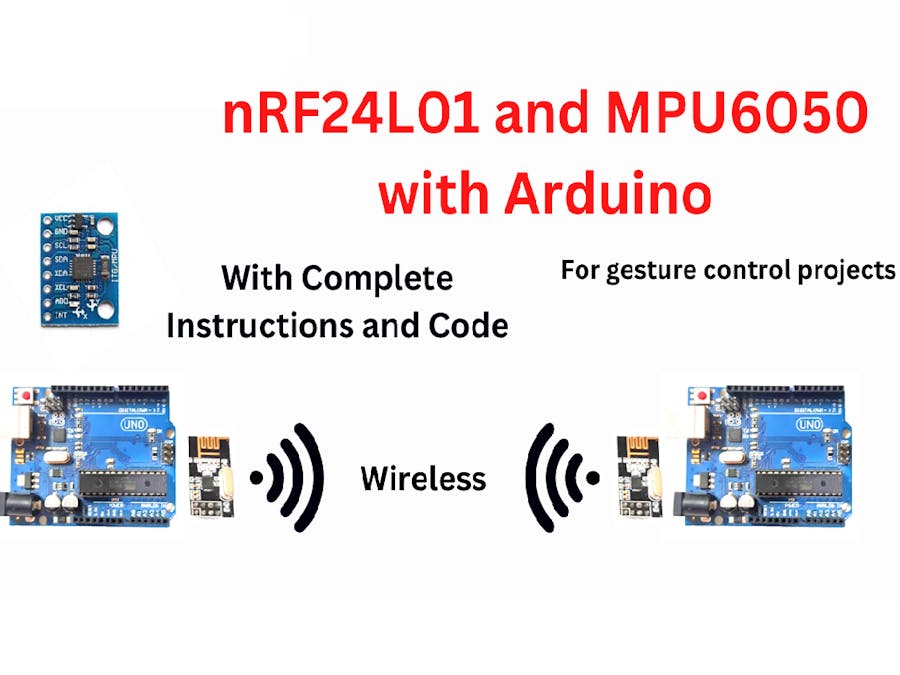
This project shows how to connect nRF24L01 Radio Module and MPU6050 with Arduino for projects that require Gesture Control

BeginnerFull instructions provided959
How to Connect nRF24L01 and MPU6050 for Gesture Control

Things used in this project

Hardware components

Arduino UNO
Arduino UNO
×2
nRF24 Module (Generic)
×2
Inertial Measurement Unit (IMU) (6 deg of freedom)
×1
Jumper wires (generic)
×1

Software apps and online services

Arduino IDE
Arduino IDE

Story

Read more

Schematics

Schematic

Make these connections on both TX and RX sides

Schematic

Make these connections on TX side only

Code

Code for TX

Arduino
Upload this code to the Arduino on the TX side
/*

  nRF24    Arduino UNO/NANO
  
  CE    -> 7
  CSN   -> 8
  MOSI  -> 11
  MISO  -> 12
  SCK   -> 13
  IRQ   -> -
  VCC   -> 3.3V
  GND   -> GND

  ---------------------------

  MPU6050   Arduino UNO/NANO
  
  Vcc    -> 5V
  GND    -> GND
  SDA    -> A4
  SCL    -> A5

*/

#include <SPI.h>
#include <NRFLite.h>
#include <Wire.h>
#include <TinyMPU6050.h>

const static uint8_t RADIO_ID = 1;              // Our radio id
const static uint8_t DESTINATION_RADIO_ID = 0;  // Id of the radio we will transmit to
const static uint8_t PIN_RADIO_CE = 7;
const static uint8_t PIN_RADIO_CSN = 8;

struct RadioPacket {
  uint8_t FromRadioId;
  uint32_t Data;
};

NRFLite _radio;
RadioPacket _radioData;
MPU6050 mpu(Wire);

void setup() {

  Serial.begin(9600);
  Serial.println("Calibrating...");

  // Initialization
  mpu.Initialize();
  // Calibration (wait for about 20s to calibrate)
  mpu.Calibrate();
  
  Serial.println("Done Calibration");

  if (!_radio.init(RADIO_ID, PIN_RADIO_CE, PIN_RADIO_CSN)) {
    Serial.println("Cannot communicate with radio");
    while (1);
  }

  _radioData.FromRadioId = RADIO_ID;

}

void loop() {

  mpu.Execute();

  while (mpu.GetRawAccX() <= -8000) {

    _radioData.Data = 1;
    sendData();
    Serial.println("front");
    mpu.Execute();

  }

  while (mpu.GetRawAccX() >= 8000) {

    _radioData.Data = 2;
    sendData();
    Serial.println("back");
    mpu.Execute();

  }

  while (mpu.GetRawAccY() <= -8000) {

    _radioData.Data = 3;
    sendData();
    Serial.println("left");
    mpu.Execute();

  }

  while (mpu.GetRawAccY() >= 8000) {

    _radioData.Data = 4;
    sendData();
    Serial.println("right");
    mpu.Execute();

  }

  while (mpu.GetRawAccX() < 8000 and mpu.GetRawAccX() > -8000 and mpu.GetRawAccY() < 8000 and mpu.GetRawAccY() > -8000) {

    _radioData.Data = 5;
    sendData();
    Serial.println("none");
    mpu.Execute();

  }

}

void sendData(){

  Serial.print("Sending");

  if (_radio.send(DESTINATION_RADIO_ID, &_radioData, sizeof(_radioData))) {
    Serial.println("...Success");
  }
  else {
    Serial.println("...Failed");
  }

  mpu.Execute();
  delay(500);

}

Code for RX

Arduino
Upload this code to the Arduino on the RX side
/*

  nRF24    Arduino UNO/NANO

  CE    -> 7
  CSN   -> 8
  MOSI  -> 11
  MISO  -> 12
  SCK   -> 13
  IRQ   -> -
  VCC   -> 3.3V
  GND   -> GND

*/

#include <SPI.h>
#include <NRFLite.h>

const static uint8_t RADIO_ID = 0;  // Our radio id
const static uint8_t PIN_RADIO_CE = 7;
const static uint8_t PIN_RADIO_CSN = 8;

struct RadioPacket {
  uint8_t FromRadioId;
  uint32_t Data;
};

NRFLite _radio;
RadioPacket _radioData;

void setup() {

  Serial.begin(9600);

  if (!_radio.init(RADIO_ID, PIN_RADIO_CE, PIN_RADIO_CSN)) {
    Serial.println("Cannot communicate with radio");
    while (1);
  }

}

void loop() {

  while (_radio.hasData()) {

    _radio.readData(&_radioData);

    int data = _radioData.Data;
    if (data == 1) Serial.println("front");
    else if (data == 2) Serial.println("back");
    else if (data == 3) Serial.println("left");
    else if (data == 4) Serial.println("right");
    else if (data == 5) Serial.println("none");

  }

}

Credits

Electronics Champ

Electronics Champ

3 projects • 9 followers
Projects based on breadboard electronics and Arduino with clear step-by-step instructions, circuit diagrams, schematics, and source code.

Comments