


Hardware components | ||||||
 |
| × | 1 | |||
 |
| × | 1 | |||
 |
| × | 1 | |||
Software apps and online services | ||||||
 |
| |||||
Hand tools and fabrication machines | ||||||
 |
| |||||
The servo motor works on a closed-loop mechanism that integrates positional feedback in order to control the rotational or linear speed and position. The servo motor is controlled with an electric signal, either analog or digital, which determines the amount of movement which represents the final command position for the shaft.
Servo motors are electronic devices, they are rotary or linear actuators that rotate and push parts of a machine with precision. Servos are mainly used on angular or linear position and for specific velocity, and acceleration.
It seemed difficult to work with servo motors due to the complexity involved in designing the circuit that can control these motors. Servo motors lie in a class of motors where you can tell the motor, what position it should move to or in what speed it should move, and its internal mechanism uses some form of feedback to ensure that the required position or velocity is achieved. This helps in reducing your efforts in ensuring that the work you have given the motor is done.
Some of the most popular servo motors allow you to control their position or velocity by having to pass to them a pulse width modulated (PWM for short) signal. Below is a photo showing an example of such a motor.
To tell these motors what angle (position) they should try to maintain, we have to send it a PWM signal every 20 ms, where the width of the pulse is proportional to the angle at which we want the motor to stop. To set an angle of 0 degrees, we will send a high signal for 1 ms, and a low signal for 19 ms, and to set an angle of 180 degrees, we will send a high signal for 2 ms and a low signal for 18 ms.
Seeing these complexities Bolt IoT platform has simplified the working of servo motor.
- Bolt WiFi Module - The Bolt Module provides the API with the help of which the servo motors runs.
Parameters and Details
Connectivity and Processing Module- ESP8266 with custom firmware
MCU- 32-bit RISC CPU: Tensilica Xtensa LX106
Power- 5V/1A DC via Micro-USB port or 5V and GND pins
Operating Voltage- 3.3V
CPU Clock Frequency- 80 MHz
MCU Internal Memory- 64 KB of instruction RAM; 96KB of data RAM
MCU External Memory- 4 MB Flash memory [QSPI]
GPIO pins- 5 Digital pins [3.3V logic]
ADC- 1 pin 10 bit ADC [0-1V input]
PWM- All 5 Digital pins capable of PWM [Software PWM]
Connectivity
WiFi- 802.11 b/g/nAutomatic AP mode if not connected to WiFiWEP/WPA/WPA2 authentication
UART- 8-N-1 3.3V TTL UART [using TX, RX, GND pins][9600 baudrate]
Cloud- Default: Bolt Cloud (https://cloud.boltiot.com/)Optional: Custom cloud using Bolt APIs
LED indicators
WiFi LED - WiFi connectivity-
1) Slow blinking: Trying to find and connect to WiFi network
2) Fast blinking: User has connected via Bolt IoT app for setup
3) Stable: Connected to WiFi
Cloud LED – Bolt Cloud connectivity-
1) Stable: Connected to Bolt Cloud
2) Off: Not connected to Bolt Cloud
3) Dim: Insufficient power/ incorrect boot
Dimensions- 35mm x 35mm
Boot Time- less than 1 second
- Servo Motor - It is controlled by the Bolt Module and can be further used as per requirement.
Specifications
- Pack of two micro servos, each SG90 come with one motor/ three servo arms and three screws.
- Operating Voltage Range- 4.8V~6.0V
- Temperature range- -55 to +75
- Dead band width- 5usec
- Exquisite small, make u realize bulid the robot project, it can suitable for a variety of RC Toys.
- Bolt Cloud - It provides the platform to run the Bolt Module and get the necessary information about it.
- Bolt Cloud Pro - It provides the necessary API for it's latest firmware update '1.4.1'.
BOLT Cloud
Link to Cloud:
Features:
1) Remote Configuration
2) Code Editor
3) Smartphone App
4) Notification(SMS & E-Mail)
5) Visualisation & Analysis
6) Remote Control
7) Device Sharing
8) OTA Updates
Hardware setupStep 1 : The Bolt WiFi module is setup to connect to the Bolt Cloud account.
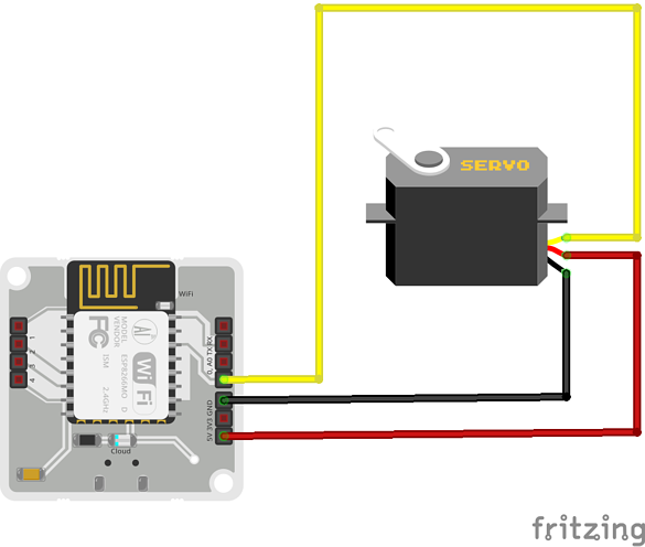
Step 2 : The jumper cables are connected from the Servo motor to the Bolt device in the given way:
The servo motor has three wires coming out of it Brown(GND), Red(Power), Orange(Signal) in color.
Bolt Module has wires Brown(GND), Green(5V) and Yellow(PWM input) in color.
- Bolt device<-- --> Servo motor
- 5V <-- -- Green wire -- -- Red wire -- --> Power
- GND <-- -- Brown wire -- -- Brown wire -- -- > GND
- Digital Pin 0 -- --> Yellow wire -- -- Orange wire -- -- > Signal
Below is a reference fritzing diagram and further below is the pictorial representation of the circuit.
Step 3 : The circuit is powered up by connecting the micro USB to the device.
Software ProgrammingStep 1 : Building the API link - To be able to control the servo motor, a link is built which is called to run the API.
In the case of the servo motor control, the link is of the form
https://cloud.boltiot.com/remote/<API key>/servoWrite?pin=<pin>&value=<angle>&deviceName=<device name>The following tags in the above link are replaced with the respective elements.
- <API key> : The API key is fetched from the Bolt Cloud.
- <pin> : The pin of the Bolt WiFi module to which the signal pin of the servo motor is connected. In our case this is 0. ( Servo motor control is available on digital IO pins of the Bolt WiFi module).
- <angle> : The angle which the Bolt WiFi module will relay to the servo motor. This angle can be between 0 and 180.
- <device name> : The device id of the Bolt module given in the form BOLTxxxxx.
After replacing the necessary elements the link now looks like this :
https://cloud.boltiot.com/remote/ed2be2b1-e577-4a80-bbf5-ee87042f0250/servoWrite?pin=0&value=0&deviceName=BOLT3847571The above link will set the motor position to 0 degrees.
https://cloud.boltiot.com/remote/ed2be2b1-e577-4a80-bbf5-ee87042f0250/servoWrite?pin=0&value=90&deviceName=BOLT3847571The above link will set the motor position to 90 degrees.
https://cloud.boltiot.com/remote/ed2be2b1-e577-4a80-bbf5-ee87042f0250/servoWrite?pin=0&value=180&deviceName=BOLT3847571The above link will set the motor position to 180 degrees.
In case of choosing a value more than 180 degrees and less than 0 degree, the prompt shows invalid value.
Step 2 : Running the API call - To run the API call, the above made links are copied and pasted into the address bar of a browser, press enter and the servo motor moves.
The following things are to be kept in mind while controlling a servo motor with the Bolt WiFi module :
- This feature is only available for Bolt Cloud Pro users. Click here to upgrade to Bolt Cloud Pro.
- The feature only works with for Bolt WiFi module which have a firmware version 1.4.1 and above. Click here to find out how to update your device firmware.
- Servo motors generally require a bit of a kick when it comes to power supplies, so if the motor is not moving the way you want it, try using a power supply with a higher current rating. (Voltage rating should be 5v).
With the help of Bolt Cloud PRO API calls, servo motor can be controlled very easily in minutes.

Comments