


Hardware components | ||||||
 |
| × | 1 | |||
 |
| × | 1 | |||
| × | 1 | ||||
| × | 1 | ||||
| × | 1 | ||||
| × | 1 | ||||
| × | 1 | ||||
| × | 1 | ||||
| × | 1 | ||||
Software apps and online services | ||||||
 |
| |||||
The HVAC air re-circulation mode on my car does not turn on by default upon start up. In my location where I drive, I needed the re-circulation to be turned on most of the time due to poor quality air from the outside, which always came as a default configuration on my other cars (no need to press it manually). Even with knowledge and access to $1000+ brand-specific vehicle communication interface (VCI) tools, there was no option to configure this function for my car. Therefore, if I cannot configure this using software, I had to do it using hardware.
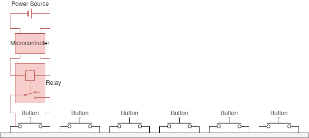
IdeaThe idea is a continuation from my previous contest-winning project (Smartwatch car remote) where a simple relay can be used to simulate a "button press" (aka. completing an electrical circuit). All I needed was a power source, a microcontroller and a relay that taps onto the existing car console button circuit.
- When I start the car, power is provided to the microcontroller.
- When microcontroller is powered, wait a short moment, then turn on the relay (press the button) once (holding around 100-200ms for normal human finger press) and release.
- After that, do nothing for the rest of the time the microcontroller is powered (until car/power is switched off)
- Repeat same logic when car is powered on again.
As a hobbyist with no knowledge on PCB design and printing, I had to source the equipment solely on ready-built options in the market, i.e. AliExpress.
Prototype using ESP-01/ESP-01SMy research landed on one of the simplest option available in the market - the ESP-01/ESP-01S relay module - a relatively compact overall package with microcontroller and relay in one (almost no soldering required). Providing it with 5V DC power (e.g. USB-A from my car phone charger ), I am already able to control the circuit with a simple code sketch (Note: The ESP-01/ESP-01S needs to be taken out and programmed separately using a programmer). A JST 2-pin connector (output) is going to be used as connection to the console button.
Prep-work on the car consoleHaving taken apart the button console, I needed to find the re-circulation button and its pins to tap onto. Using button schematics I found on the internet, I tapped onto the two pins using a JST 2-pin connector (polarity does not matter at this point), and routed the wires through the existing PCB holes (luckily no drilling required!)
Following this, I also had to source 12V DC power from the car that is only powered when the car is started. I tapped into the cigarette lighter socket wiring (no detailed photos for this) using a standard DC 5.5mm barrel jack.
Unregulated DC power from the car ranges from 12-14V, which needed to be stepped-down/regulated to fixed 5V. I used a Mini560 to provide fixed 5V output. However, this increases the overall physical package size of this project, which now fits in a 61x36x25mm electronic enclosure box.
Connected the input and output wires, added kapton tape, and drilled some holes into the enclosure box:
Now, the project is more or less complete, but I was not satisfied with a few points:
- Overall package size (61x36x25mm) of this setup is quite big, might be a little more difficult to fit behind the car console. The relay and the Mini560 are the largest components.
- Relay switching is loud/noisy (although some might argue this audible feedback proves that it is working)
- ESP-01/ESP-01S is overkill for this project (I did not need the WiFi/Bluetooth capabilities of this board)
- The relay is also overkill for this purpose (normally for switching circuits with larger currents).
I knew I had to downsize the relay and the Mini360. Further research led me to using optocoupler for switching and changing the microcontroller to a Digispark ATTiny85 (USB-C) clone.
Pros:
- Way smaller overall package size - 42x22x12mm.
- The Digispark ATTiny85 includes an onboard 78L05 voltage regulator that takes care of the 12V DC power input - no additional step-down converter necessary. Otherwise it can also be powered by 5V (USB-A from phone charger)
- The Digispark ATTiny85 includes a USB-C connector for programming (no additional programmer is necessary).
- An optocoupler is optimal for handling the switching in this use case, compared to any kind of relay (reed relay and solid state relay have all been considered)
- No "clicking" sound when switching (could be a 'con' to some).
Cons:
- The optocoupler is polarity sensitive - take note of the wires tapped to console button pins.
- The Digispark ATTiny85 is sensitive to power supply fluctuations, and may cause unexpected behavior when working with unregulated DC power from the car. An additional diode may be necessary, else source 5V power from a USB phone charger.
- The Digispark ATTiny85 may experience brownouts (losing memory) from unregulated DC power (see above).
- The Digispark ATTiny85 has a bootloader that delays the startup time by 6-8 seconds by default. (I do not mind this delay for my use case, the code needs to be modified slightly)
- More soldering necessary than the ESP-01/ESP-01S.
- The Digispark ATTiny85 is a little tricky to setup for programming (deprecated libraries/core files)
Final connections:
- DC barrel jack soldered onto ATTiny85 VIN and GND pins.
- ATTiny85 P1 and GND soldered onto optocoupler input +/- (J1) using white 26AWG wires.
- JST connector soldered onto optocoupler OUT and GND (J2)


Comments