/*
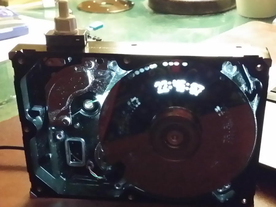
How to use an old HDD as a Nipkow disc to display time.
_________________________________________________________________
| |
| author : Philippe de Craene <dcphilippe@yahoo.fr |
| Any feedback is welcome |
|
_________________________________________________________________
Materials :
1* Arduino Uno R3 - IDE version 1.8.10
1* HDD with a 3 phases delta motor, the one used was a 24 coils motor
1* SN754410 to drive the motor
1* infrared motor speed detector, otherwise 1 IF LED and 1 fast IF phototransistor detector
1* DS1307 module to keep time
4* 3W LEDs
1* push-buttons
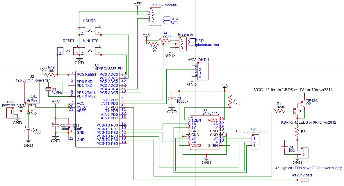
Arduino Uno / ATMega328p pinup :
- io A0 (analog 0) PC0 pin23 => minutes setup input
- io A1 (analog 1) PC1 pin24 => hours setup input
- io A4 (analog 4) PC4 pin27 => SDA output for DS1307
- io A5 (analog 5) PC5 pin28 => SCL output for DS1307
- io 2 (numeric 2) PD2 pin4 => IF detector input
- io 3 (numeric 3) PD3 pin5 => DHT11 temperature & hygrometry sensor
- io 9 (numeric 9) PB1 pin15 => 1/3 output motor driver
- io 10 (numeric 10) PB2 pin16 => 2/3 output motor driver
- io 11 (numeric 11) PB3 pin17 => 3/3 output motor driver
- io 12 (numeric 12) PB4 pin18 => power output for ws2812 LEDs
Versions chronology:
V0.7 - 2 feb 2020 => 1st working version with a 4 holes Nipkow disc, various unsuccessfull tests with 5, 6 and 8 holes
V1.0 - 5 feb 2020 => considerably increase of stability by drivong the motor with Timer1 interrupts
V1.1 - 7 feb 2020 => add temperature and hygrometry with shift digit for displaying
V1.2 - 8 feb 2020 => chararcters size from 4x5 to 5x5 - disk holes 1.5mm
V1.3 - 4 mar 2020 => DHT11 + installed on PCB
V1.4 - 23 mar 2020 => sleep after the show + improvment of stability
*/
#include <TimerOne.h> // https://github.com/PaulStoffregen/TimerOne
#include <TimeLib.h> // https://github.com/PaulStoffregen/Time
#include <DS1307RTC.h> // https://github.com/PaulStoffregen/DS1307RTC
#include <DHT.h> // https://github.com/adafruit/DHT-sensor-library
// https://github.com/adafruit/Adafruit_Sensor
#include <avr/sleep.h> // http://www.gammon.com.au/forum/?id=11497
#include <avr/power.h>
// Arduino Uno pinup
const byte motorPin1 = 9;
const byte motorPin2 = 10;
const byte motorPin3 = 11;
const byte ledPin = 12;
const byte synchroPin = 2;
const byte MbuttonPin = 0;
const byte HbuttonPin = 1;
const byte dhtPin = 3;
// Parameters
//__________________________
// motor speed parameter
const int final_motorDelay = 1500; // ~1400 under 5V,
// 1500 => 36.128 ms for 24 coils
// 1970 => 47.660 ms
// synchro & display parameters :
//
// Timer1.initialize(motorDelay/pixelsbycoil) => set the total number of pixel = 24*(pixelsbycoil)
// lineLengh = digiLengh*(total number of digits)
const byte pixelsbycoil = 15; // so the total number of pixels is 24*15 = 360
const byte lineLengh = 72; // 360 total pixels divide 5 lines = 72 pixels per line
const byte digitLengh = 6; // must be a multiple of lineLengh, 5 for characrter + 1 'space' give 12 digits
//byte message[6] = { 10, 10, 10, 10, 10, 10 }; // contains the list of characters to display
// autostop
unsigned int autostop = 180; // 300 for 300 seconds
// define the characters to display // PROGMEM ne fonctionne pas ????
const byte character[][5] = {
{ 0b01110, 0b10001, 0b10001, 0b10001, 0b01110 }, // 0
{ 0b00100, 0b01100, 0b00100, 0b00100, 0b00100 }, // 1
{ 0b01110, 0b10001, 0b00010, 0b00100, 0b11111 }, // 2
{ 0b11110, 0b00001, 0b01110, 0b00001, 0b11110 }, // 3
{ 0b10001, 0b10001, 0b11111, 0b00001, 0b00001 }, // 4
{ 0b11111, 0b10000, 0b11110, 0b00001, 0b11110 }, // 5
{ 0b01110, 0b10000, 0b11110, 0b10001, 0b01110 }, // 6
{ 0b11111, 0b00001, 0b00010, 0b00100, 0b01000 }, // 7
{ 0b01110, 0b10001, 0b01110, 0b10001, 0b01110 }, // 8
{ 0b01110, 0b10001, 0b01111, 0b00001, 0b11110 }, // 9
{ 0b00000, 0b00000, 0b00000, 0b00000, 0b00000 }, // 10 = ' '
{ 0b00000, 0b00100, 0b00000, 0b00100, 0b00000 }, // 11 = :
{ 0b00100, 0b00000, 0b01100, 0b00100, 0b01100 }, // 12 = I
{ 0b10000, 0b10000, 0b10000, 0b10000, 0b11111 }, // 13 = L
{ 0b11111, 0b10000, 0b11110, 0b10000, 0b10000 }, // 14 = F
{ 0b01110, 0b10001, 0b11111, 0b10001, 0b10001 }, // 15 = A
{ 0b11111, 0b00100, 0b00100, 0b00100, 0b00100 }, // 16 = T
{ 0b11111, 0b10000, 0b11110, 0b10000, 0b11111 }, // 17 = E
{ 0b00100, 0b01010, 0b00100, 0b00000, 0b00000 }, // 18 =
{ 0b01110, 0b10000, 0b10000, 0b10000, 0b01110 }, // 19 = C
{ 0b10001, 0b00010, 0b00100, 0b01000, 0b10001 }, // 20 = %
{ 0b00000, 0b00000, 0b00000, 0b00000, 0b00100 }, // 21 = .
};
// Other variables
//__________________________
// motor variables
unsigned int motorDelay = 50000; // initial motor step delay
byte indice = 0;
byte pixelsbycoilCount = pixelsbycoil;
// synchro & display
volatile bool synchroFlag = false; // interrupt flag become true for each infrared detection
int pixelCount = 0; // count the number of steps between 2 interrupts
byte digitCount = 0; // counter for digit syncho
byte lineNumber, digitNumber, digitNow;
int twodigits; // buffer for shift display
// time
time_t t;
byte H, Hd, Hu, M, Md, Mu, S, memo_S, Sd, Su, dp;
bool deuxpoints = false;
// DHT11 sensor
DHT dht(dhtPin, DHT11);
byte T, Td, Tu, U, Ud, Uu;
// animation
byte i = 0, j = 0, k = 0;
bool shift = false;
//
// SETUP
//_____________________________________________________________________________________________
void setup() {
pinMode(motorPin1, OUTPUT);
pinMode(motorPin2, OUTPUT);
pinMode(motorPin3, OUTPUT);
pinMode(ledPin, OUTPUT);
pinMode(synchroPin, INPUT);
pinMode(HbuttonPin, INPUT_PULLUP);
pinMode(MbuttonPin, INPUT_PULLUP);
pinMode(dhtPin, INPUT_PULLUP);
Serial.begin(250000);
Serial.println("Start....");
// the function to get the time from the RTC DS1307
setSyncProvider(RTC.get);
t = now();
H = hour(t);
M = minute(t);
// temperature & hygrometry at startup because it is a very long process
dht.begin(); // initialise the DHT11 sensor
while( T == 0 ) {
T = dht.readTemperature();
U = dht.readHumidity();
// just a short show bedore starting the motor
digitalWrite( ledPin, HIGH); delay(10); digitalWrite( ledPin, LOW);
}
Td = T/10; Tu = T%10; Ud = U/10; Uu = U%10;
// start interrupt with IR sensor on Arduino Uno pin 2
attachInterrupt(digitalPinToInterrupt(synchroPin), Synchro_detect, FALLING);
// documentation : https://www.arduino.cc/reference/en/language/functions/external-interrupts/attachinterrupt/
// start motor sequence
SpeedupMotor();
// start synchro timing on interruptions (only once the motor is running)
Timer1.initialize(motorDelay/pixelsbycoil);
// motorDelay is the delay for 24 pixels as it is a 24 coils motor
// motorDelay/2 makes 48 steps=pixels
// motorDelay/4 makes 96 steps=pixels
// motorDelay/8 makes 192 steps=pixels
// motorDelay/10 makes 240 steps=pixels
// motorDelay/12 makes 288 steps=pixels
Timer1.attachInterrupt(BlinkLed); // BlinkLed is called (motorDelay/pixelsbycoil) times per interrupt
} // end of setup
//
// Synchro_detect : what is done at each interruption
//____________________________________________________________________________________________
void Synchro_detect() { synchroFlag = true; }
// BlinkLed : what is done at each Timer1 period
//____________________________________________________________________________________________
void BlinkLed() {
if( synchroFlag == true ) {
pixelCount = 0; // reset the trame pixel count at each interrupt
digitNumber = 0; // reset the digit position
synchroFlag = false;
}
if( pixelsbycoilCount == pixelsbycoil ) { // change the motor drive sequance 24 times per interrupt
MotorControl();
pixelsbycoilCount = 0 ;
}
if( digitCount == digitLengh ) { // each time a new digit treatment must start
digitCount = 0;
lineNumber = pixelCount / lineLengh; // get actual line number
if( digitNumber == lineLengh/digitLengh ) digitNumber = 0; // reset the actual digit position each new line
if( shift == true ) {
if( ++k > 40 ) k=0; // k is the shift speed
if( digitNumber == 0 && k == 0 ) {
j++;
if( j == 35 ) shift = false; // the number of digit to shift
} // end of test oncePerSecond
} // end of test shift
else j=0;
byte message[46] = { 10, 10, Hd, Hu, dp, Md, Mu, dp, Sd, Su, 10, 10, 12, 13, 10, 14, 15, 12, 16, 10, Td, Tu, 18, 19, 10, 17, 16, 10, Ud, Uu, 20, 21, 21, 21, 10, 10, Hd, Hu, dp, Md, Mu, dp, Sd, Su, 10, 10 };
digitNow = character[message[digitNumber+j]][lineNumber] & 0b00011111;
digitNumber++; // digit position in the line is increased
} // end of test digitCount
if( (digitNow & 0b10000) == 0b10000 ) PORTB |= B00010000; else PORTB &= B11101111; // PB4 set to HIGH (io 12) digitalWrite is very slow
digitNow = digitNow << 1; // shift left to be able to compare the next bit
digitCount++;
pixelsbycoilCount++;
pixelCount++; // increase pixel counter
} // end of BlinkLed()
//
// LOOP
//_____________________________________________________________________________________________
void loop() {
// after the code below all is run only once per second
memo_S = S;
S = second();
if( memo_S == S ) return;
// time set
if( analogRead(HbuttonPin) < 2 ) {
t = now(); t+=3600; RTC.set(t); // set the RTC and the system time to the new value
H++;
}
if( analogRead(MbuttonPin) < 2 ) {
t = now(); t+=60; RTC.set(t); // set the RTC and the system time to the new value
M++;
}
// time display
if( S%2 == 0 ) deuxpoints =! deuxpoints;
if(deuxpoints) dp = 11; else dp = 10;
if( S == 0 ) M++;
if( M > 59 ) { M = 0; H++; }
if( H > 23 ) H = 0;
Hd = H/10; Hu = H%10;
Md = M/10; Mu = M%10;
Sd = S/10; Su = S%10;
// display animation
if( S == 30 ) shift = true;
// autostop
if( --autostop == 0 ) GotoSleep();
} // end of loop
//
// SpeedupMotor()
//_____________________________________________________________________________________________
void SpeedupMotor() {
unsigned long memo_tempo = 0;
//unsigned long synchroNow = 0, memo_synchroNow;
// pseudo-logarithm increase of rotation speed
while( motorDelay > final_motorDelay ) {
if(synchroFlag == true) { // done for each IR sensor detection (synchro interrupt)
synchroFlag = false;
if( motorDelay > 15000 ) motorDelay = motorDelay - motorDelay/5; //15000
else if( motorDelay > 11000 ) motorDelay = motorDelay - motorDelay/10; //10000 -> 12000
else if( motorDelay > 2000 ) motorDelay = motorDelay - motorDelay/100; //1900
else motorDelay--;
/*
// display startup disk turn duration
memo_synchroNow = synchroNow;
synchroNow = micros();
Serial.print(motorDelay); Serial.print("\t"); Serial.println(synchroNow - memo_synchroNow);
*/
} // end of test synchroFlag
if( (micros() - memo_tempo) > motorDelay ) { // time to change the step
memo_tempo = micros();
MotorControl();
}
} // end of while motorDelay
} // end of SpeedupMotor()
//
// MotorControl()
//_____________________________________________________________________________________________
void MotorControl() {
if( ++indice > 5 ) indice = 0; // the counter to generate ghe 3 phases motor drive sequence
switch( indice ) {
case 0: PORTB |= B000010; break; // output 9 to HIGH
case 1: PORTB &= B111011; break; // output 10 to LOW
case 2: PORTB |= B001000; break; // output 11 to HIGH
case 3: PORTB &= B111101; break; // output 9 to LOW
case 4: PORTB |= B000100; break; // output 10 to HIGH
case 5: PORTB &= B110111; break; // output 11 to LOW
} // end of switch
} // end of MotorControl()
//
// GotoSleep()
//_____________________________________________________________________________________________
void GotoSleep() {
power_all_disable (); // turn off all modules
noInterrupts(); // required with IDE 1.8.x
set_sleep_mode(SLEEP_MODE_PWR_DOWN); // keep Timers in working states
sleep_enable(); // enable the sleep mode
interrupts();
for( byte p=2; p<19; p++) {
pinMode( p, OUTPUT );
digitalWrite( p, LOW );
}
sleep_cpu(); // activate the sleep mode
} // end of GotoSleep()


_ztBMuBhMHo.jpg?auto=compress%2Cformat&w=48&h=48&fit=fill&bg=ffffff)


Comments