

Hardware components | ||||||
 |
| × | 1 | |||
| × | 1 | ||||
| × | 3 | ||||
 |
| × | 1 | |||
Software apps and online services | ||||||
 |
| |||||
Hand tools and fabrication machines | ||||||
 |
| |||||
 |
| |||||
 |
| |||||
Noise pollution at traffic junctions is a serious problem in urban cities. People honk excessively at red lights even when they cannot move forward, creating unnecessary stress, air vibrations, and health issues.
This project introduces a smart traffic light system that punishes honking during red lights. The idea is simple yet powerful:
- A WS2812B RGB LED Matrix simulates a traffic light (red → orange → green).
- A sound sensor continuously monitors the environment.
- If the red light is ON and honking exceeds a defined decibel threshold, the red timer resets and starts over.
- A MAX7219 7-segment display (4-in-1) shows the countdown timer. If honking causes a reset, the display shows the message:
"Honk More, Wait More"
This system not only simulates a traffic light but also enforces behavioral correction, teaching drivers that excessive honking will only delay their wait further.
🎯 Objectives
- Create a traffic light simulator controlled by ESP32S3 Sense.
- Integrate a sound sensor to detect excessive honking.
- Add a punishment mechanism by resetting the red signal timer.
- Display real-time countdown and messages using MAX7219.
- Raise awareness about noise pollution through technology.
- XIAO ESP32S3 Sense (controller + Wi-Fi/Bluetooth support).
- WS2812B 8×8 RGB LED Matrix × 3 (to simulate traffic lights).
- MAX7219 4-in-1 8-digit 7-segment display (for countdown + warnings).
- Sound Sensor (Analog/Digital Microphone Module) (to detect honking).
- Breadboard and jumper wires.
- 5V USB power supply or battery pack.
Traffic Light Control
- The ESP32S3 controls three WS2812B matrices.
- LEDs represent Red → Orange → Green in sequence.
Timings:
- Red → 10 seconds
- Orange → 3 seconds
- Green → 7 seconds
Sound Monitoring
- The sound sensor continuously measures ambient noise.
- If noise level > threshold dB while red is active, the system treats it as honking.
Punishment Mechanism
- The red light countdown resets to max value if excessive honking occurs.
- The cycle is delayed, punishing impatient drivers.
Visual Feedback
- The MAX7219 display shows the countdown timer.
If honking resets the timer, it flashes:
- "HONK MORE, WAIT MORE" before continuing the countdown.
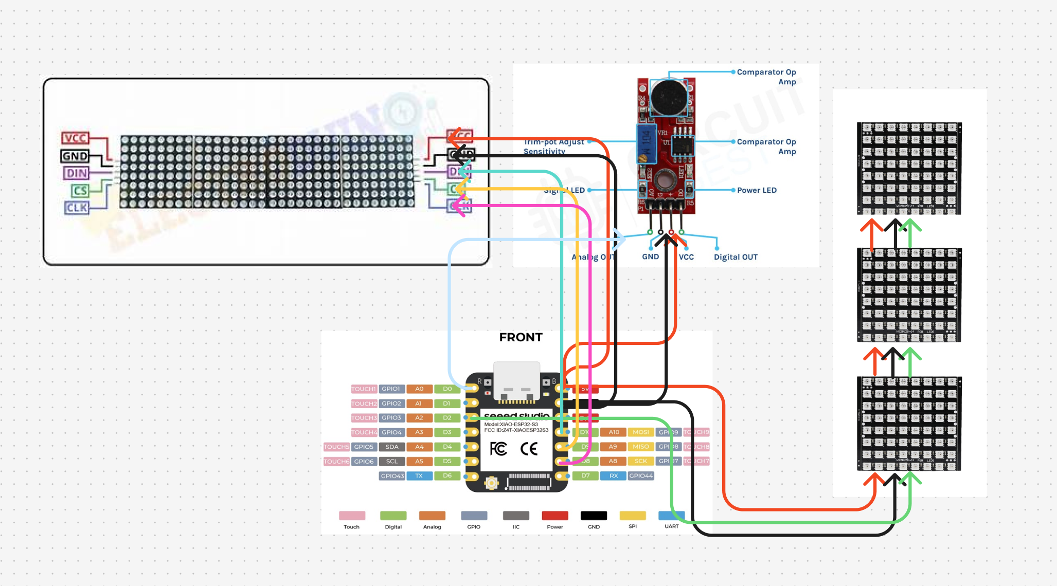
1. Wiring the WS2812B Matrices
- WS2812B works on single-wire data communication.
- Connect all 3 matrices in series (Data Out of one → Data In of next).
Pin connections:
- DIN → ESP32S3 GPIO pin (e.g., D2)
- VCC → 5V
- GND → GND
⚠️ Important: Use a 470Ω resistor on the data line and a 1000µF capacitor across VCC & GND to protect LEDs.2. Connecting MAX7219 Display
The MAX7219 uses SPI for communication.
- VCC → 5V
- GND → GND
- DIN → D10
- CS → D8
- CLK → D9
Most sound sensors have AO (analog out) and DO (digital out).
- If using AO, connect it to ESP32S3 ADC pin (e.g., A0).
- If using DO, set threshold using onboard potentiometer and read as digital input.
Example:
- AO → ESP32S3 A0
- VCC → 3.3V/5V
- GND → GND
Libraries Required
Adafruit_NeoPixel(for WS2812B control).LedControl(for MAX7219).Arduino.h(for ESP32 core functions).
Core Logic
- Traffic light cycles normally.
- Sound sensor value is checked only during Red state.
- If above threshold → Reset timer.
- Update MAX7219 display accordingly.
Before running the full project, find a good threshold so normal noise doesn’t trigger resets.
Upload this tiny sketch, open Serial Monitor (115200), watch values in quiet vs honk/clap:
// Quick sound calibration for XIAO ESP32S3 Sense
#define SOUND_PIN A0

void setup() {
  Serial.begin(115200);
}

void loop() {
  int v = analogRead(SOUND_PIN);
  Serial.println(v);
  delay(50);
}
- Note a quiet value (e.g., 400–800).
- Note a honk/clap value (often much higher, e.g., 1500–3000).
- Pick a threshold somewhere between (example: 1200).
- You can always refine later.
- Shows centered countdown on MAX7219
- Normal sequence: RED → YELLOW → GREEN → RED
- During RED only: if sound exceeds threshold → scroll warning once, then reset RED and continue
- Uses your earlier pin choices (D2 for WS2812, D10/D8/D9 for MAX7219, A0 for sensor)
/***** Honk More, Wait More — Smart Traffic Light *****
   Board: Seeed XIAO ESP32S3 Sense
   LEDs : 3x WS2812B 8x8 matrices daisy-chained (total 192 LEDs)
   Display: MAX7219 4-in-1 (4x 8x8) dot matrix
   Sensor: Analog sound sensor on A0
********************************************************/
#include <Adafruit_NeoPixel.h>
#include <MD_Parola.h>
#include <MD_MAX72xx.h>
#include <SPI.h>

/* ---------- USER SETTINGS (tune these) ---------- */
#define RED_SEC     30       // red duration (seconds)
#define YELLOW_SEC  5        // yellow duration
#define GREEN_SEC   20       // green duration
#define BRIGHTNESS  50       // WS2812 brightness (0-255)
#define SOUND_PIN   A0       // analog input for mic
int SOUND_THRESHOLD = 1200;  // <-- set after calibration

/* ---------- WS2812 (all 3 matrices on one pin) ---------- */
#define WS_PIN      D2
#define LED_COUNT   (64*3)   // 192

// index ranges for each color section
#define IDX_RED_START     0
#define IDX_RED_END       63
#define IDX_YEL_START     64
#define IDX_YEL_END       127
#define IDX_GRN_START     128
#define IDX_GRN_END       191

Adafruit_NeoPixel strip(LED_COUNT, WS_PIN, NEO_GRB + NEO_KHZ800);

/* ---------- MAX7219 (MD_Parola) ---------- */
#define HARDWARE_TYPE MD_MAX72XX::FC16_HW
#define MAX_DEVICES   4           // 4 modules = 32x8
#define MAX_DATA_PIN  D10
#define MAX_CLK_PIN   D8
#define MAX_CS_PIN    D9

MD_Parola P = MD_Parola(HARDWARE_TYPE, MAX_DATA_PIN, MAX_CLK_PIN, MAX_CS_PIN, MAX_DEVICES);

/* ---------- Helpers for LEDs ---------- */
void fillRange(int startIdx, int endIdx, uint8_t r, uint8_t g, uint8_t b) {
  for (int i = startIdx; i <= endIdx; i++) strip.setPixelColor(i, r, g, b);
}
void allOff() {
  for (int i = 0; i < LED_COUNT; i++) strip.setPixelColor(i, 0, 0, 0);
  strip.show();
}
void showRed() {
  allOff();
  fillRange(IDX_RED_START, IDX_RED_END, 255, 0, 0);
  strip.show();
}
void showYellow() {
  allOff();
  fillRange(IDX_YEL_START, IDX_YEL_END, 255, 165, 0);
  strip.show();
}
void showGreen() {
  allOff();
  fillRange(IDX_GRN_START, IDX_GRN_END, 0, 255, 0);
  strip.show();
}

/* ---------- MAX7219 text helpers ---------- */
void showCountdownCentered(int seconds) {
  char buf[8];
  snprintf(buf, sizeof(buf), "%02d", seconds);
  P.displayClear();
  // centered, static print (no animation effects)
  P.displayText(buf, PA_CENTER, 0, 0, PA_PRINT, PA_NO_EFFECT);
  P.displayAnimate();  // render immediately
}

void scrollMessageOnce(const char* msg, uint8_t speed = 40) {
  P.displayClear();
  P.displayText((char*)msg, PA_CENTER, speed, 0, PA_SCROLL_LEFT, PA_SCROLL_LEFT);
  while (!P.displayAnimate()) {
    // animate until finished
    // (no delay here to keep it responsive)
  }
}

/* ---------- Sound sampling ---------- */
// Take a quick burst of samples, use the peak to decide
bool honkDetected() {
  int peak = 0;
  for (int i = 0; i < 40; i++) {           // ~quick 40-sample burst
    int v = analogRead(SOUND_PIN);
    if (v > peak) peak = v;
    delayMicroseconds(500);                // short spacing
  }
  return (peak > SOUND_THRESHOLD);
}

/* ---------- One light "phase" with optional honk reset ---------- */
void runPhase_RedWithHonkReset(int durationSec) {
  showRed();
  int t = durationSec;
  while (t > 0) {
    showCountdownCentered(t);

    // Check for honk only during RED
    if (honkDetected()) {
      // Show warning, then reset timer
      scrollMessageOnce("HONK MORE, WAIT MORE", 40);
      t = durationSec;              // reset to full red
      showRed();                    // ensure red stays on
      showCountdownCentered(t);
      // brief pause so number stays visible after scroll
      delay(300);
      continue; // go to next loop iteration without decrement
    }

    delay(1000);
    t--;
  }
}

void runPhase_Static(int durationSec, void (*showColor)()) {
  showColor();
  for (int t = durationSec; t > 0; t--) {
    showCountdownCentered(t);
    delay(1000);
  }
}

/* ---------- Setup & loop ---------- */
void setup() {
  Serial.begin(115200);

  // WS2812 init
  strip.begin();
  strip.setBrightness(BRIGHTNESS);
  strip.show();
  allOff();

  // MAX7219 init
  P.begin();
  P.setIntensity(2);     // 0..15; adjust to taste
  P.displayClear();

  // Optional: small hello scroll
  scrollMessageOnce("SMART TRAFFIC READY", 35);
}

void loop() {
  // RED
  runPhase_RedWithHonkReset(RED_SEC);

  // YELLOW
  runPhase_Static(YELLOW_SEC, showYellow);

  // GREEN
  runPhase_Static(GREEN_SEC, showGreen);
}
- Treats the three 8×8 panels as one long strip of 192 LEDs.
- Lights only one color section at a time (red range, yellow range, green range).
- Uses MD_Parola to show a centered two-digit countdown on the MAX7219.
During RED only, it takes a quick burst of analog reads and looks at the peak value; if it’s above SOUND_THRESHOLD, it:
- Scrolls “HONK MORE, WAIT MORE” once,
- Resets the RED timer back to full,
- Continues counting down again.
I chose a simple cardboard box which is a scrap to build a DIY enclosure . If you have a facility to 3D printing you can go for that.
Firstly i chose a box of desired size.
Then i covered it with black A4 and cut out necessary holes for the LED and covered the hole with A4 for aesthetic reason and mounted it on a pvc pipe stand.
This is the final look
- Run the system with normal cycle (no honking).
- Check sound sensor readings in quiet vs honking conditions.
- Tune the threshold value until it reliably detects honks but ignores background noise.
Observe the reset mechanism:
- Honk → Timer resets → Display shows punishment message.
- Replace WS2812B with a real traffic signal light module for field testing.
- Store honking violations in ESP32 memory and push logs to a cloud server via Wi-Fi.
- Add a camera module for license plate recognition of violators.
- Integrate with IoT dashboards for live monitoring.
"Noise pollution affects everyone. Patience saves time, honking wastes it."🌍 Social Impact
- Reduces noise pollution in urban areas.
- Teaches discipline and patience to drivers.
- Can be integrated into real smart city infrastructure.
- Enhances road safety and reduces stress levels.


Comments