

Hardware components | ||||||
_ztBMuBhMHo.jpg?auto=compress%2Cformat&w=48&h=48&fit=fill&bg=ffffff) |
| × | 1 | |||
Software apps and online services | ||||||
| ||||||
One of the most important things when playing guitar is making sure that the instrument is in tune. Even the best guitar player will not sound any good with an out-of-tune guitar. Tuning guitars by hand using a standard tuner has always been common, but an automatic tuner makes things much easier, and more fun! This Arduino-based project will tune your guitar for you.
Here is a video showing the project in action: https://www.mathworks.com/videos/automatic-guitar-tuner-using-simulink-and-arduino-1501787185047.html
Overview
The figure above shows an overview of the automatic guitar tuner.
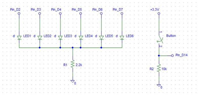
- The push button is used to select the string to tune
- A six-LED display is used to indicate which string has been selected
- The gripper connected to the motor is used to turn the tuning peg until the string is in tune.
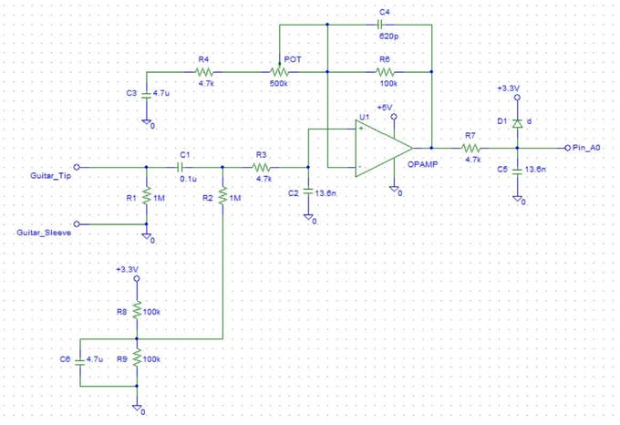
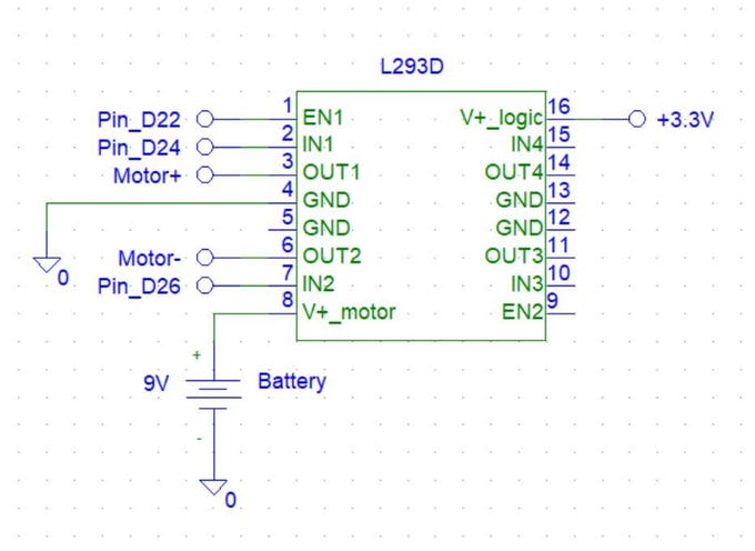
The inputs and outputs are controlled by the four circuits mentioned above: a digital input circuit for the push button, an analog audio input circuit for the guitar, a digital output circuit for the LED display, and a motor-driving circuit for the tuning peg gripper. These four circuits interact with an Arduino Due, which is running an algorithm that was developed using Simulink.
Audio Input CircuitThe guitar is connected to the tuner via a standard guitar cable. The end of a guitar cable has two connections, called the tip and the sleeve. One end of the cable will be connected to an input jack, which has leads for the tip and the sleeve. I soldered wires onto these leads to connect the tip and the sleeve to the audio input circuit.
I would recommend using a TL972 op amp for this circuit. It is a very-low-noise, rail-to-rail amplifier that can operate at very low supply voltages.
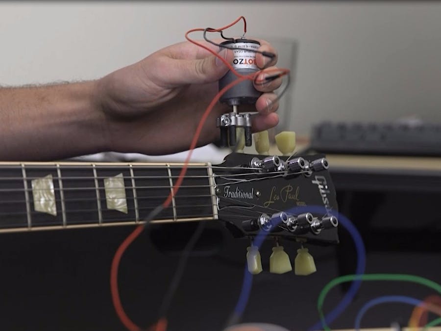
Motorized Tuning Peg Gripper
I couldn’t use just any DC motor for this project. I needed a geared motor with a low speed and a high torque. The motor I used has a speed of 6 RPM and a maximum torque of 613 oz-in. It has a voltage range of 3-12 V, and so I used a 9 V battery as the power source.
On the shaft of the motor, I assembled a simple gripping mechanism using a clamp hub, four screws, and some tape.
Software
I used Simulink and its support package for Arduino to develop the algorithm for the tuner. Simulink is a block-diagram environment used for developing algorithms and modeling dynamic systems. The support package allows me to read from and write to pins on the Arduino using Simulink blocks. Using the software’s external mode capabilities, I can simulate an algorithm on the Arduino with automatic code generation and tune parameters while the simulation is running, without having to recompile any code. I can then deploy the algorithm to the hardware for standalone execution. The model I created is shown below.
External mode allows the use of scope blocks to monitor portions of the algorithm while it is running on the hardware. This is especially useful to monitor the digital input from the button and the analog input from the guitar. From the button scope, we can see that the input changes from 0 to 1 when the button is pressed.
I want this change from 0 to 1 to trigger a change in the selected string. This is known as a rising trigger. I created a Stateflow chart called “Select String” that has six states, one for each string, and changes from one state to the next based on this rising trigger input. Here is a more detailed look at the Stateflow chart.
Upon entry to each state, the LED pin for the corresponding string is set to high. Upon exiting each state, the pin is set to low. I chose the low E string, the lowest of the six strings, as my default. When I first power the tuner on, it will start in this default state.
There are seven outputs on the Stateflow chart: one for the LED for each of the six strings, and one called “periodRange,” which I will discuss later. The six LED outputs go straight to Arduino digital output blocks to power the appropriate LED on or off.
Now let’s look at the audio processing portion of the model. The guitar signal comes in through the analog input block. I set the sample time of the block to be 0.0002 seconds for a 5-kHz sampling rate. When I played the guitar and opened the audio scope block, I was able to see a waveform like the one below.
The scope block helped me tune the potentiometer in the audio circuit to change the gain of the input. The gain should be set as high as possible without the waveform’s peak reaching the maximum value of 1023. This will allow for the most precise reading of the signal.
When the guitar is not played, the input signal should be a flat line somewhere between 500 and 700. In my case, it was around 550. It is important to know this value because the tuner should process the audio only when there is a note being played. I chose a value of 575, just above this flat line, to be my threshold. The audio will be processed only when the signal is above this threshold value. Since Simulink allows me to tune parameters while a simulation is running, I was easily able to set my threshold value.
When a single note is played on a guitar, the waveform generated is periodic. The period of the waveform corresponds to a certain musical pitch. The tuning algorithm estimates the pitch of the string by determining the period of the waveform. I wrote a MATLAB function that performs this pitch estimation, and included it in my Simulink model using the MATLAB function block. To determine whether the string is in tune, the MATLAB function needs an input indicating what range of periods is considered in tune for each string. This is the output “periodRange” from the Stateflow chart. The function determines whether the pitch of the string is too high, too low, or in tune based on the period range, and generates outputs for the motor accordingly.
The outputs of the MATLAB function are the three pins that control the motor. These outputs go straight to Arduino digital output blocks.
Once I ensured everything was just right with my algorithm, I was able deploy it to the hardware so that it could run standalone, without being connected to the PC and independent of Simulink.
Now I can tune my guitar automatically!
All the necessary files for this project are available here:
Digital Input and Output Circuits
Audio Input Circuit
Motorized Tuning Peg Gripper


Comments