


Hardware components | ||||||
 |
| × | 1 | |||
 |
| × | 1 | |||
| × | 2 | ||||
| × | 1 | ||||
 |
| × | 1 | |||
Software apps and online services | ||||||
| ||||||
Maybe you know watt meters you can put it into the socket. It's good when you want to sometimes read the power consumption. What about the situation you need to measure the power consumption periodicaly (and remotely and save to database)?
The idea was simple: Create own's Watt Meter from Big Clown modules. It will be special extension cord using any current sensor connected to core module pins and measuring current in wires, Then (because of we know the voltage in electric network) calculate power consumed.
We learned the formula in primary school :)
P = U * I
Magnetic field is created around the wire through which the current passes. A coil placed to this field converts it back to the current. A/D converter in the Core Module can't read currrent but voltage. Fortunately we can simply convert measured quantity using a resistor and measure voltage spend on it.
Resistance is calculated using the Ohm's law. As we know maximum allowed voltage on ADC pins and maximum current generated on the sensor, the required resistance can be calculated:
U = I * R => R = Umax / Imax
- Umax = 3.3V (max voltage that can be measured by Core Module).
- Imax = 5mA (from the sensor specification).
In this case the maximum resistance is 660 Ohm, but for sure the resistor should be smaller. Because of the smallest resistor I had home was 680 Ohm I used two in parallel with total resistance 340 Ohm and max expected voltage on A/D converter 1.7 V,
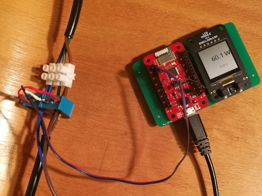
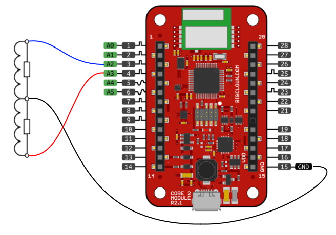
The current have to be measured only on one wire (not whole power cord) - brown/black (L) wire or blue (N) wire. So I used two HWTC 5A/5mA - for both black and blue wires, to be able compare the current difference (will be described below). The yellow-green cable is ground and no current should pass through it.
SchemeIn the electrici network there is alternating current. It means the current direction is changing - 50 times every second (50Hz) - every 20ms. And direction of the current induced on the sensor's coil is chaning too... and voltage orientation on resistor too.
A/D converter reads actual voltage (positive values) and is able to read it every 3 ms (tested). During one period of electricity we can measure voltage 6-7 times. Because of we need the peak voltage (maximum) it's required to repeat messuring during few periods to really catch the peak.
For direct current it's simple to calculate power consumed - just multiply the voltage and curent (see formula above). For alternating current it's bit complicated. First we have to calculate something called Effective Current - "converts" sine curve to the rectangles with the same area. The operation is called Root Mean Square and basically it means multiplying the peak current by 0.707 (for sine waves).
Now we have everything we need to calculate power consumed. Final formula is:
P = Ue * (Umax / R) * ratio * 0.707
- Ue - voltage in electrical network (230 V)
- Umax - max measured voltage on resistor
- R - resistance of the resistor (340 Ohm)
- ratio - sensor's measuring ratio (1000)
The code was the simplest part of the project. Principles of measurement of the alternating current are described above. The main part of application's code is placed into measure_current() method. You can see the while loop used to measure peak voltage on input. The period of measuring is declared to 100ms which corresponds to 5 periods of 50Hz.
The current passing the sensor is calculated using the known resistance. Current on wire is defined by sensor measuring ratio (1000 in case of HWTC 5A/5mA). And finally the effective current is calculated.
float measure_current(bc_adc_channel_t channel)
{
    uint16_t adc;
    uint16_t max = 0;
    bc_tick_t start = bc_tick_get();
    while (bc_tick_get()<start+MEASURING_TIME)
    {
        bc_adc_get_value(channel, &adc);
        if (adc>max)
            max = adc;
    }
    float voltMax = (max * VDDA) / 65536.f;
    if (voltMax<ZERO)
        voltMax = 0;

    float rms = sqrt(2)/2;
    float currentSensor = voltMax / R;
    float current = currentSensor * RATIO;
    float currentEff = current * rms;

    return currentEff;
}
Power consumption is calculated in the application_task() method.
void application_task(void)
{
    float c1, c2;
    float power;
    bool warning;

    c1 = measure_current(COIL_1);
    c2 = measure_current(COIL_2);

    power = U * (c1 + c2) / 2;
    warning = abs((c1-c2)*1000)>1;

    bc_radio_pub_float(RADIO_TOPIC, &power);

    lcd_write((c1 + c2) / 2, power, warning);

    bc_scheduler_plan_current_from_now(MEASURING_PERIOD-2*MEASURING_TIME);
}
Then the measured currency and power consumption is shown on LCD display. The measurement is repeated every 5 seconds.
You can modify your parameters in declarations on the beginning of the code. Also you can change pins used to measure - I used A2 and A3 pins.
You can see the power consumed is sent over the radio to the dongle in my laptop. From there it can be re-sent to the database - most probably laying on cloud.
Why battery?When I prepared the cable to measuring I thought: "Why I run Core Module by batteries when there is enough of electricity around?" I found switched power supply with 5 V output - small black box (literally :) and soldered power and USB cable to it (power cable is connected to electricity, USB cable connected to Core Module).
Final test: I connected Core Module to the power supply and inserted the plug into the socket - text on LCD appears and no smoke here :)
Then I connected 60W lamp to my "extension cord" and switched it on. You can see the result:
At this moment just "sexy" housing is missing.
And why the currency have to be measured on one wire only? And why I used two sensors?When the current goes through the wire it creates electromagnetic field that is oriented according by direction of curent. When the circuit is closed then current in black (I) and blue (I') wires are identical but in oposite direction. The electromagnetic fields generated by wires also have oposite drection. So the fields are eliminated each other.
But what happend when someone touch the opened circuit? Current passing through black wire (I) is splitted between blue N wire (In) and body (Ip).
I = In + Ip
Part of current (Ip) passing through the body to the ground is dangerous for human. When the code detects difference between currents measured on black and blue wire (possible dangerous situation) the warning appears on display.
W A R N I N GBe careful when playing with 230V, It's dangerous and circuit should be checked by someone with appropriate education.


Comments