

Hardware components | ||||||
 |
| × | 2 | |||
Software apps and online services | ||||||
 |
| |||||
Hand tools and fabrication machines | ||||||
 |
| |||||
A few weeks ago I made a project involving a Bresser weather station and a LilyGO LoRa32 circuit, all installed at home, for managing weather datas and relay them to the network servers Weather Underground and APRS/CWPO (here the link to the project) to publish local data worldwide.
Happy for the result, it works 24/24 and 7/7 at my home, I push myself a bit more to satisfy a long time ago desire: to put a weather station at the local paragliding take-off to have wind speed, wind direction, temperature and humidity and share these data for everybody. But the take-off is on the top of a mountain and there we don't have electric power nor WiFi...
Wunderground, APRS, CWOP? What are these?For an answer and some other details please have a look to the above link mentioning my previous project.
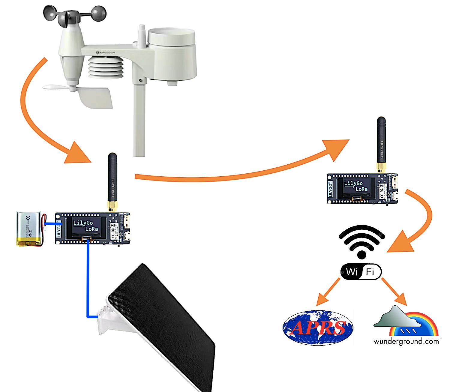
The Circuit:The project is simple from an electronic point of view, in the sense we do not have to make PCBs, find and solder components, etc. but just assembling something to contain the ready-to-use LilyGO boards in plastic boxes and something more. The weather station in all-in self contained with AA batteries that should last for a year or more, put the unit on the top of a pole following included instructions in the box when you buy it. Choose a solar panel with pole support and point it to the south at 45° (southern hemisphere installation should point to the north...). The remote LilyGO that stays near the station on the mountain has to have a rechargeable battery installed, just buy the suggested size and plug-in its connector; the same thing with the solar panel, just plug-in to same LilyGO to recharge the battery with the sun. Another LilyGO stays at home powered by USB and connected to the internet via WiFi.
The complex part has been writing the software installed on the two LilyGO, one at transmitting side on the mountain and one at receiving side at home. But now the software is written and tested, so no problems at the moment!
The weather station transmit every 24" the data that is captured by the near installed LilyGO (on the mountain) that retransmit every 1 minute the data to the other LilyGO (at home). At this point the home LilyGO relays data via WiFi to desired servers for publication as per Wunderground (every 7') and/or APRS/CWPO (every 11'), the sketches will do the job.
Of course you need a WiFi access point in the area you install the home LilyGO. The LilyGO at home it is powered by USB with a consumption around 55-90mA, in case of blackout it just powers down like your WiFi access point; if you like to keep the circuit on during blackouts you have to add a rechargeable battery even to home LilyGO using the onboard 2 pins connector, the USB will provide to recharge it as the MCU board already got a recharging circuit; a battery model 102535 850/1050 mA/h fits perfectly my 3D box; be sure the connector is a 2 pin JST 1.25mm and the (+) and (-) wires are in the correct position; the remote LilyGO needs a rechargeable battery, not an optional, and the solar panel to recharge it via USB.
How much distance may I place the receiver LilyGO? My home is around 4Km (-109dBm radio signal) away from the top of the mountain but I did some tests with success at 10Km away (-120dBm radio signal). The two LilyGO was in sight each other. Of course less distance with no obstacles is better.
- 2 x LilyGO LorRa32 version 1.6.1. (other version should be fine but I tested this one only)
- 1 x 9W Solar Panel with mini USB connector (to directly power the transmitting LilyGO on the mountain)
- 1 x mini USB Cable (to directly power the receiving LilyGO at home)
- 1 x 102535 3.7V Li-Ion 1050mA/h rechargeable battery (for remote LilyGO)
- 1 x 5in1 Bresser Weather Station (the outdoor sensors unit is enough, it is not needed the indoor display unit)
- 2 x 3D printed box to contain the two LilyGO (look at the download section the files ready to be printed that I made); using a translucent filament for printing gives the possibility to see LED activity trough the cover;
- 1 x waterproof plastic box + something to pass-trough the cable from the solar panel
- Hexagonal M2 plastic spacers, 8x10mm and 8x20mm, and M2 screws to keep the two LilyGO in place. In reality LilyGO got only 2 holes on PCB to pass the screws, the two on the left; leave unscrewed the bottom and the top right corners spacers; four expansions of the 3D cover will, together with the two screws, keep in place the LilyGO;
To pass the sketches to LilyGO boards with Arduino IDE be sure to choose the right board and relative settings as per following screen-shot:
The sketches at the moment, for long range communication from the mountain to the home, are using the EU standard frequency around 868Mhz at 25mW of power following the rules. You may modify these settings according to your Country rules. The Bresser I utilised is a 5in1 model that actually transmits around 868Mhz (to the near LilyGO) with a 6in1 protocol (looks strange but that is, ask to Bresser programmers why), it means that the sketch is modelled to use this protocol. If you utilise another model you have to adjust the code accordingly and modifying the file "WeatherSensorCfg.h" of the library too. The 5in1 model is enough because are used wind speed, wind direction, temperature and humidity sensor values; actually is not used the rain sensor so a station with more sensors is not useful.
For the main work the sketch on remote LilyGO uses the BresserWeatherSensorReceiver library version 0.37.0, author Matthias Prinke; other libraries are present in code, of course, like the one for the OLED display, WiFi, Watchdog, Preferences (EEPROM), etc.
First of all, the home LilyGO sketch updates its time via internet (this is done every 3h), then stays listening on the 868Mhz channel the remote LilyGO station transmitting every 1 minute, and receives the data from it. If you enabled the Wunderground section it will send by WiFi to the Wunderground server every 7 minutes the weather data; the similar thing is done to the APRS server, if enabled by you, every 11 minutes. The times schedule could be modified a bit i.e. 5 minutes and 10 minutes.
The remote LilyGO does its job to receive data every 24" from the Bresser weather station and to relay data on 868Mhz; to transmit and receive data between the two LilyGO I utilised a very similar protocol as Fanet but on a different frequency channel to avoid interference on both sides. The circuit stays in deep sleep mode for around one minute then wake up to do its job and go back sleeping: in this way it saves a lot of battery! The sleeping time is done a bit randomly regarding the time so may lasts 45" to 75". After wake up, if the battery level is below 3.2V, warning battery level, it comes back sleeping immediately (without transmitting anything) with a new programmed wake up time after 30 minutes instead of the usually 1 minute; this is done to preserve the Li-Ion battery life waiting for more sunlight to be recharged. When the battery level reach again a working level over 3.2V the "game" restarts. The battery as usual can be recharged at max till 4.2V, this is done automatically by internal recharge circuit. During my tests and experience with my installation, the battery, during a winter night without sun from 17:00 to 08:00 (15h in the dark at 45° of latitude north in Europe), passes from 4.2V to 3.8V; in the morning after sunrise the solar panel needs 1-3h to recharge the battery to full level again depending of weather of the day, shining sun or cloudy. With two raining days in a row the battery could reach the warning level of 3.2V, so expect the transmitter LilyGO stops to transmit till the next day with some radiation from the sun. You could increase the battery capacity from the suggested 1050mA/h to 2000/3000mA/h, your choice, but take in account a new 3D box as mine is small for a bigger battery. You could increase the power of the solar panel too...
It is enabled a Watchdog so if for some reasons the sketch stuck for more than 60" it will provide to auto reset and try again; the WD will reset the circuit even if one of the "failure counters" is higher than 9: NTP time, WiFi access, WUNDER server access, APRS server access, REBOOTS caused by Watchdog or other, NETWORK access and BRESSER receiving. Usually the circuit and the software run well without difficulties but with these counters you have the possibility to keep under control the problems.
The display of the home LilyGO stays ON for 10 minutes after power-up, then it goes OFF to save the efficiency of the screen. So, do not be afraid if the display will switch off! Even the LilyGO on the mountain goes off but every minute in deep sleep mode as already spoken above.
If you keep the circuit connected to Arduino IDE, activating the Serial Monitor, you may see a rich log explaining what the software is doing. My experience says to avoid to put the circuit too close to the WiFi access point (1-2m away is fine), in this way you will have less communication errors.
Using Mac OSX and Arduino IDE, to upload the sketch maybe you have to install the USB serial driver for this circuit, more info here: https://www.wch-ic.com/downloads/CH34XSER_MAC_ZIP.html
Failure counters and statuses are shown in the "Comment" text sent with APRS packets in a kind of telemetry, very useful because you may look at them remotely (see aprs.fi "raw" packets). In the Comment is present a text like this: (T0A1R0W1N0E0I110V41S0+), the meaning is:
- Tn = number of NTP time update errors
- An = how many times APRS server not reached
- Rn = number of reboots by Watchdog at home LilyGO
- Wn = how many times Wunderground server not reached
- Nn = network / WiFi not available, number of times
- En = wrong packets received regarding the data length
- Ixxx = receiving radio signal level in dBm, absolute value (110 = -110dBm)
- Vyy = battery level in tenths of volt (V40 = 4.0v)
- Sn = number of reboots by Watchdog at remote LilyGO on the mountain
- +/- = Bresser sensors AA battery status (+) = OK, (-) = needs change
The home LilyGO counters are set to zero everyday at 00:00 time. If one counter is more than 9 the Watchdog resets the circuit. It is normal to have a few numbers, 1 or 2, during 24h on counters like W, A or N, even R; usually they stay at zero and it means everything is running like a Swiss clock!
Before compiling and testing the home LiliGO you have to specify your Access Point name and Password of your WiFi. One of the most important setting is to specify the ID of the remote LilyGO because will be received/accepted only that one and only one: look at the serial monitor of the remote LilyGO to read the instrument ID, so put that value in the code of the home LilyGO. An alternative way to read the remote LilyGO ID is to look at the home LilyGO serial monitor log and read the "not accepted" ID as different than the expected one.
- char WiFi_SSID[40] = "XXXXX"; // put your SSID WiFi access point
- char WiFi_PASS[40] = "YYYY"; // put your PASSWORD WiFi access point
- String IDtoReceive = "XXYYZZ"; // remote weather station ID to receive;
Another thing to adjust is your timezone; do not forget to specify your Wunderground weather station ID and PASSWORD, if activated by the constant "isWUNDERactive=true"; you obtain these information when you register your weather station in Wunderground website. Of course you have to insert your APRS data access if activated by the constant "isAPRSactive=true"; if you are not interested in the Wunderground or the APRS you have just to put the respective value to "false" and avoid to set other respective values (ID, PASS, callsign, pass, etc.). I think the APRSserver is fine to leave as is the one already present in the code as it is a rotating one, not a fixed one. Here the things you should modify:
- const long utcOffset = +3600; // timezone for local time in sec (+3600" = +1h)
- char mywunderID[40] = "IDIDID"; // your Wunderground weather station ID
- char mywunderPASS[40] = "PsWPswP"; // your Wunderground password
- const char myAPRScallsign[40] = "CALLSIGN-13"; // your ham radio callsign or CWOP, user
- const char myAPRSpasscode[40] = "12345"; // your ham radio passcode or CWOP, pass
- const char myAPRSlatLon[40] = "4018.23N/01435.16E"; // your weather Station Position DDMM.MMy/DDDMM.MMx
The sketch is derived from the decoding example code made by Matthias Prinke (read his copyright notes at the beginning of the code); before compiling you have to personalise WeatherSensorCfg.h as specified by the author; I modified the following line numbers commenting/uncommenting as necessary; very important is the line number 93 where you could enter your Bresser station ID (mine is 0xD144 as written below) but only if you have more than one around; instead I suggest to leave it empty { }. If you leave it empty you will receive any station ID, but if you ENTER IT PLEASE NOTE that the ID will change every station reset or battery change (randomly) so you need to keep it updated manually! I specified the station ID just because I had two and wanted to received just one, but, I repeat, is better to leave it empty { } considering that at the top of the mountain it will be just your station alone!
- 89: #define SENSOR_IDS_EXC { }
- 93: #define SENSOR_IDS_INC { 0xD144 }
- 101: // #define WIND_DATA_FIXEDPOINT
- 105: // #define BRESSER_5_IN_1
- 106: #define BRESSER_6_IN_1
- 107: // #define BRESSER_7_IN_1
- 108: // #define BRESSER_LIGHTNING
- 109: // #define BRESSER_LEAKAGE
- 151: #define ARDUINO_TTGO_LoRa32_V21new
In the remote LilyGO you may specify the coordinates of the weather station position too, latitude and longitude in degrees, so the Fanet like radio packet will contain this information.
- const double FANET_latitude_deg = 40.12345; // latitude of the remote station
- const double FANET_longitude_deg = 11.01234; // longitude of the remote station
I wish you an happy installation on the top of the mountain and at home, enjoy the weather data with this interesting project. Have fun de IV3CGM !
I would thanks to Daniele DB to finance the items and encourage me to make the software, all the mechanical parts are made by him! Thanks as well to those contributed to it as David DC and especially Nicola P. holding the receiving side at home.
NEWS / Updates:- 06.02.2026: published the 3D enclosure box on my GrabCAD account; these files are in download section too.
- 20.02.2026: added a complete description of the "telemetry" present in APRS Comment and some pictures of weather charts and maps;


Comments