

Hardware components | ||||||
_wzec989qrF.jpg?auto=compress%2Cformat&w=48&h=48&fit=fill&bg=ffffff) |
| × | 1 | |||
 |
| × | 1 | |||
 |
| × | 1 | |||
 |
| × | 1 | |||
| × | 1 | ||||
| × | 1 | ||||
| × | 1 | ||||
| × | 1 | ||||
| × | 1 | ||||
| × | 1 | ||||
| × | 2 | ||||
| × | 1 | ||||
| × | 1 | ||||
| × | 1 | ||||
Software apps and online services | ||||||
 |
| |||||
| ||||||
| ||||||
Hand tools and fabrication machines | ||||||
| ||||||
Woodworker/ retired industrial automation engineer on steampunk kick. Have designed Rick & Morty gadgets and now want to take it to the next level.
Bought one of the full kits and wanted to see how far I could push it. Along the way I had to invent connector shrouds, cable holders, and lots of different 3D printed mounting hardware.
Once the wiring was decided and the mounts created the main components were mounted on a 12x12 piece of scrap lexan. I've got other lexan for the four LCD displays, optical pickups and indicators.
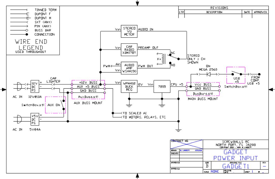
PowerThe unit is powered by a 12 volt DC car adapter connected to a TO-220 7805 three terminal +5 volt regulator. The +5, Gnd, SCL, and SDA lines are connected to buss bars for easy connection.
I tried a couple of different terminal shields. The ones with posts don't keep a firm grip on the individual DuPont wires and the pin density makes adding new connections a fifty-fifty chance of knocking another pin loose.
Soldering to buss bars was chosen for simplicity and reliability. Mounts for 12 ga. buss bar wires were 3D printed and mounted. The mounts have the buss signal embossed for error free wiring.
Didn't really consider the dissipation on that poor TO-220 package when dropping 12v to 5v at 2a. The drop is 7v @ 2a or 14W! After a while I noticed a curl of smoke from the mounting stand off. Oops! Need a Plan B.
Disabling USB power:One issue I have with running off the USB is that you have to unplug the project to turn it off. This will rapidly wear out the connectors. My solution was to splice in a switch on the USB power line so I can turn the project off and on without pulling the cables apart.
Everything is soldered and covered with HS tubing. The cables are banded with HS to keep them from forming runs.
The DuPont cables have individual pins the need to be inserted. With most daughter cards having from two to eight pins, getting all to engage at once is a problem. Shrouds installed over the individual pins and glued in place allow the pins to be mated as a group as well as providing a labeling location.
Heat shrink tubing is used to prevent the ribbon wires from unzipping. Additionally it is used to separately group power leads and signal leads so wiring could be easily verified.
Each of the daughter cards supplied with the development kits have had cables and shrouds attached, as well as the mounting hardware loosely attached. This assembly was then bagged to keep all the necessary components in one place. This has greatly simplified installing as each assembly has been tested and is ready to go.
Most everything is working that's been installed. The stepper motor is next to go in.
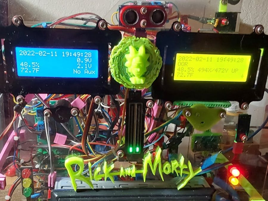
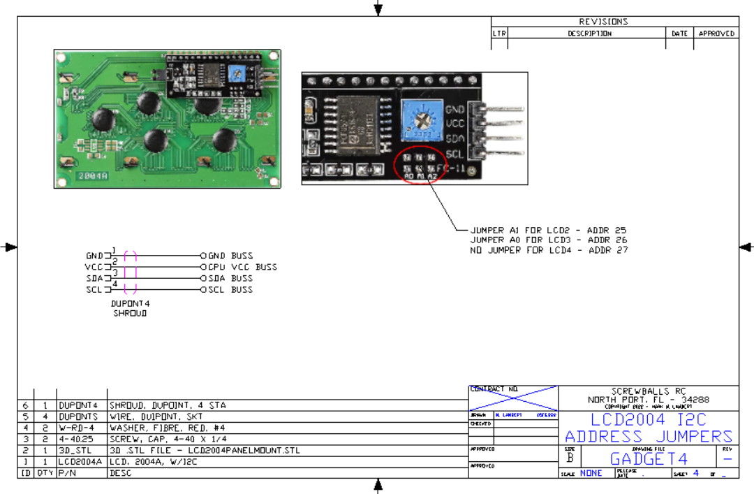
The dual 20x4 LCDs are handy as I've got diagnostic values being displayed from each sensor for easy debug in addition to the normal serial.print debugging messages.
One device I'm having issues with is the touch sensor. this should be a trivial item but seems to have a very noisy output. It looks like it's chattering instead of giving a solid DO. The device also has an AO so maybe I can filter that.
The knock sensor is planned to be tied into the touch sensor so the user has to touch a certain screw of many on the panel and then trigger the knock. But that isn't going to happen until I get the touch sensor working.
I've got the 5k pot, the internal +5 power and the external +12V supply all tied to AI's so the system can monitor it's internal voltages.
The 5k pot is looped into the servo and they track.
I want to wire up the DC motor but I also want to implement Motor direction/Enable logic so I need to add a 74LS00 quad NAND gate and an H-driver to reverse the motor. It's not complex, but it's gotta be built. Maybe give me something to solder into the breadboard area of the screw shield.
The RTC is sorta working, it's stuck at the set time. I know I'm missing something simple but not highest on the priority list.
The sonar sounder was initially wired backward, reversing the bits in the code solved that without tinkering with the hardware.
The LDR for sundown sense is working. I've got it tied into the relay bank to turn on a load at dark. The relay can take 5A so I can control a significant load. Dunno WHAT yet, but I'm working on it.
Another thought. Could couple the laser with the LDR and make a pulsed beam system. This way the system can't be dazzled by an outside source. We poll with the beam off and check to see that it's dark. Then we turn the laser on and look again. If its now bright we're ok and turn the laser back off. Since we've seen the beam in both states under our control we can be assured that the LDR is only seeing our beam and we can detect "dazzle".
The remote EPS-01 is wired but is useless without someone else to comm with so that hasn't been touched.
The DHT-11 is working fine. I have another one built into an EPS card that I need to figure out. Why doesn't ANYTHING Arduino come with a pointer to the docs?
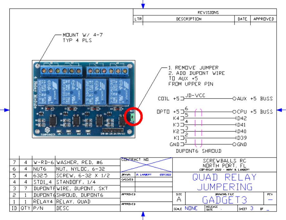
The four relays all work.
- VU Meter Power
- VU Source, NC - Radio, NO - AO
- VU Mode - Pulse to change display mode
- Darkness Relay, NC - Light, NO - Dark
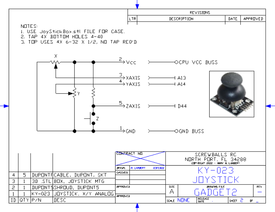
Joystick is working, two analogs and a button. Mounting is still iffy. I can screw down the four corners but I have to buy a box of 100 6-32 x1" screws when I only NEED *4*. (sigh)
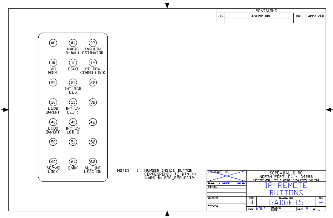
IR remote was working on breadboard. Shouldn't be hard to get running again. Have only decoded a few buttons. Need to get all 21 deciphered. This will allow remote control of the many functions of my Rick Box™.
Connections should be much more reliable since everything is mounted and not pulling on each other. I put some feet on the base. The entire rig can be lifted and moved without disturbing the wiring.
Design Details:I like to keep an IO usage map. Here is what I've got so far. This is just a snapshot of a live document so the final in the project.zip will be different than what is shown here:
It's important to keep the spreadsheet, hardware, and software in sync.
I wish that TinkerCAD had a way to dump the object as a standard three view with isometric so you could easily document the objects being 3D printed. The final on this project will either have the.gcode files attached, or a download like, so you, dear reader, will be able to make the bits and bobs. Some of the stuff might get cad'ed but I'm not about to draw stock piece parts.
The wiring is cluttered and I doubt the schematic drawing tools will be much use. I'll try it and see, but there are a LOT of wires. It's all neatly designed, but the tangle at the buss bars is unavoidable in a prototype.
Going to try to get started on the smoked Lexan front panel. Both the front and rear are 12x12 and the plan is to frame it so that the innards can be seen (darkly) thru the front. Small sizes (under a sheet) are hard to find in smoked or transparent/translucent colors. This is "grey" but isn't very dark. The displays will show up cleanly, but the innards may be too visible. We'll see.
Since this is a "Rick" box I've already 3D printed a couple of portals. Just gotta figure out where to add them.
That's about it for today. Manana!
16JAN22Well I ordered a buck-boost converter from Velleman and put it between the +12V main power supply and the 7805 local +5 regulator. I preset the output voltage to 8V so now the 7805 is only dropping 3v instead of 7, this should cut the power down from 14W to 6W at 2A.
Naturally I had to make a base for it. I think vendors should start including .STL file links for the ever growing 3D printer community. This particular card has no mounting holes, none. How do they think we can use these in permanent setups if the only way to mount it is with glue?! The 3D printer is a godsend for this.
I know the current design is at the PS limit from the USB because the LCD's are dimmer and they blink when the servo kicks, drawing more current. With the 7805 off +12V everything was brighter.
Time to get the front panel built. The connections on the main panel have stabilized since the pieces are all bolted down and no longer putting stress on the the leads. Mounting up the front panel will help with the remaining parts.
Bought a stereo 5W amplifier kit (also from Velleman) that I was planning to boost the FM radio card output with but that might be on hold as the FM card is being fussy. The leads snapped and the holes and card are so small that I[m having trouble getting them rewired. The world has miniaturized everything but my fingers. My fallback is a car radio stereo. It can be bluetooth controlled instead of having to write code. Either way the plan includes a stereo LED bar graph VU meter. Several of the relays will be used to control the source and display modes.
The stereo gain pot is remotely mounted.
The filtered PWM DO's that Arduino uses as AO's can only drive to Vcc. The bargraph runs 0 to 12V. So I'm going to use the amp to boost the signal so I can program the Arduino to twiddle the lights when otherwise idle. At music time it'll switch over to live audio automagically. Need to pair up the relays or find a compatible DPDT relay to do the signal switching.
Since the power is now stable, I can get back to coding and getting the remaining balky items running right (RTC, touch sensor, BM280 baro).
One of the little things I do is mark the pin 1 location on the edge of the card with a Sharpie. This allows me to orient the cable while looking at the end with the card mounted instead of having to get on top with a flashlight to find the square padded pin.
StructureThe design is starting to form. It will be two 12x12 pieces of Lexan (front smoked, back clear) sandwiching the guts between them. The whole thing will sit on a pedestal with a secret compartment built in. On the top will be another storm glass and color changing LED's.
Stepper motor board was hooked up but not tested. Problem was not enough current to drive it. When I ran the test module I could feel the stepper trying to cog but not actually moving. I figured I just didn't have enough +5.amps. Plan C is that I bought a wall wart type 5v @ 4A power supply. Last night I printed up a mounting box so I can switch off the power without having to unplug.
MORE POWER! UHH! UHH! UUH!The kit comes with a teeny tiny ninety gram force servo. It's working but with the plan for it to open the wooden door to a secret compartment I figured something beefier might be needed. I found this beast at a local hobby shop for $20.
Their pin-out is the same. But I assume the current needs are different. So I'm adding a 2nd +5 for just the motor & servo. This should keep the LCD's from blinking when the servo kicks. I'm using a 12 V @ 10 Amp power supply so a few A in +5 shouldn't load it too much. The radio is 4x50w with a 10 amp fuse.
So I'm adding another set of power buss bars, +12V, +5V, and Gnd. It's printing now.
Panel Fab:The panel mounting has begun. The 2004 LCD displays are like the eyes. The bargraph the nose, and the radio the mouth. The LDR and IR Remote mount below the LCD's. I've even printed a couple of L brackets to mount the two lexan halves.
The panel still has its protective skin. It's transparent smoked grey underneath. LDR in black, IR in red. Bargraph vertical. Everything mounts with 4-40 or 6-32 hardware. I use red fiber washers under the screw heads so not to damage PC traces. Nylock nuts eliminate lock washers and can't rattle off or be unscrewed without interior access.
27Jan2022Just cut nearly the last mounting holes in the smoked Lexan and decided it was time to build for real.
Here are some build pics. I printed and they're big enough to let the front panel to stand on its own.
Most of the cables are short, but I have M-F DuPont wires to spare so I'm printing a batch of cable clamps to hold the extensions in place. Since both ends are needed I'm not going to bother cutting, adding shrouds, and re-soldering, ready made cables.
Clockwise from top left.
- Panel free stands
- Echo ranger has hole cutouts. Blue & yellow LCD's. Bargraph.
- Traffic lights are at both ends of stereo.
- Panel & control board starting to connect.
Clockwise from top left.
- Amp module, Aux power buss, amp gain pot.
- Main power and I2C buss bars.
- Six relays, naturally the logic is inverted on the quad board vs the two single relays.
- Panel wiring with extended cables.
The power system is complex. The total draw is over the limit for the Mega so an Auxiliary +5 VDC power supply is used. The original design is to be powered by a 12 VDC, 10A power converter but the Aux +5 has it's own 5 VDC, 4A converter. The aux supply will power the servos, motors, relays and other significant loads. In order to insure that the unit knows that the Aux power is available or not the 0-25 VDC input module was hardwired to the Aux +5 buss so the Mega can know if it can flex it's muscles, as it were.
Another issue is the continuous connection between the PC with the USB cable. I added a switch on the USB power so I can run the computer without running the project and without having to plug & unplug. A switch was added on the Aux +5 for the same reason.
The +12 VDC/10A power buss is used to run the radio, audio amp, and bargraph display as well as being down converted to +8 with a switcher and then to +5 via a 7805 linear regulator. Between shedding some of the loads to the Aux supply and using a switching pre-regulator that should keep the 7805 from melting the standoffs (again).
The IO's got remapped again, but all seems to be working (mostly). I had attempted to solder directly to the IO expander but that was a mistake. I had to build another one and swap out it and the Mega.
The second Mega will be used in the outside portion of the project.
Got a nice beefy servo to use opening the door. it should have more than enough torque. Naturally it needed a mount. The 3D printed stands are quite sturdy and I can tap the holes so no nuts are needed to mount the servo. I've mentally roughed out the linkage and with a transfer bar a 90 deg move should flip the door down. Going to move it slow like it weighs a TON. Wish I could make a squeeky hinge sound effect as it does. Hmmm.
This project is going to be BIG! the front panel is 12" by 12" and the box will be about 18" tall, 12" wide, and at least 6" deep. (Why is editing numbers so hard on the tablet?)
Things are starting to light up and display.
Clock is now ticking, gotta set the time, but things are moving forward.
Most things are passing diags, but things like the ESP needs the far end up. The motors and servos are waiting on final power check, I'm running low on outlets.
Working on getting all the IO's up at once. Joystick is working but loose. Was thinking of mounting it on the panel with standoffs but when I couldn't get the FM radio modules to work the joystick to control them was no longer needed. I have motors that could be controlled by the joystick so I might still have a use, just not wanting to mount it on the panel. So I designed a little 2-1/4" x 2-3/4" box with mounts and a cable hole. Here it is. The top has a spherical recess and not just a hole so the fit to the top of the joystick is very close. It took 5 hours to print and I think it came out well.
The module has four #4 thru holes on a.80" x 1.05" grid for mounting. The posts need to be tapped for #4 but the lid screws will accept 6-32 x 1/2" screws as-printed - no thread cutting needed. The corners were rounded for comfort. Cable exits left.
Moving forward:Been adding all sorts of random functionality. So far:
- Biker Magic 8-Ball
- Insulin Estimator
- PO Box Combination Lock with Servo actuator
- Stereo Hardware VU Meter support
- Remote control
Also have been using input devices in unusual ways. The insulin estimator and the PO Box lock both use the potentiometer on an AI as a numerical data entry device. It enters a scaled number directly with the insulin estimator and simulates the knob of a combination lock in the lock module.
Closing in on the mechanical design. As you can see the plastic bars are holding the unit upright and aligned in near the final physical configuration. Additionally the flip down door mechanism is solidifying. The servo motion and mounting have been more-or-less resolved and some of the mounting bits printed.
The project is finally almost ready for final fab. The plan is to cover the top and both sides with Lexan and put a wooden base on the bottom. SWMBO likes being able to see inside the box and all the blinkey lights.
I repurposed the stepper motor driver card to drive some 12V automotive LEDs mounted on the inside. One is RGB color changing and two are UV to make the 3D printed parts really pop.
One problem is that the LEDs on the motor driver card are very bright, especially when all four are on at once. I printed a diffuser cap to cover the LEDs but still allow the state to show.
It's superglued in-place.
I also added some Traffic Light decorations to the two R/Y/G panel displays. I use the separate R/Y/G LED displays instead of a single RGB LED so that red/green color blind people can tell by position which color is lit.
The case is coming along:
I think it looks pretty cool. The whole thing is solid. You can pick it up and flip it around and nothing moves or falls out (except the servo). The wiring isn't as bad as it looks. The cable shrouds really help keep everything connected.
Gadget Project - Power Supplies
Quad Relay Jumpering
LCD2004 I2C Address Jumpers


_t9PF3orMPd.png?auto=compress%2Cformat&w=40&h=40&fit=fillmax&bg=fff&dpr=2)


Comments