

Hardware components | ||||||
 |
| × | 1 | |||
| × | 1 | ||||
| × | 1 | ||||
| × | 1 | ||||
| × | 1 | ||||
| × | 1 | ||||
| × | 1 | ||||
Software apps and online services | ||||||
 |
| |||||
Hand tools and fabrication machines | ||||||
| ||||||
| ||||||
As a new product on the market, the Sony's Spresense board provides significant Arduino compatibility with some key built-in capabilities. In order to check Arduino compatibility and leverage some of these capabilities, the following project was put together leveraging an onboard GPS/GNSS, SD card, and audio interfacing. This might be called the "driver habit project" and is intended to inspire and guide you on Spresense integration with a capability for which you might find your own variation and use.
Like all projects of this kind, you may encounter issues relative to hardware or software component variations for which you may need to investigate further to resolve.
Basics of the ProjectTo make use of the key features of the Spresense, I decided to focus on monitoring and alerting on driver habits. The best way to do this is through an OBD-II connection on vehicles built after 1996. OBD-II is an industry standard for supporting vehicle operations and diagnostics, however globally there are variations in the interface that may need to be adjusted.
WARNING: Since this project is designed to interface with a vehicle and be operational while driving, it should NOT be viewed, touched, or adjusted during a vehicles movement. The design is intended to be engage before, and disengaged after the vehicle is properly parked.
This is a walkthrough of the project and not a packaged solution with all outlined details. Everything is provided or referenced in the article for replication, however it does require some sophistication to pull it together and work through any variation issues possibly encountered. Later, further consideration can be given to better integration, easier activation, packaging, power sourcing, etc. In addition, variations of vehicle capabilities may require additional thought, or customization.
This article will seperate out the basics of OBD integration and readings, from the specific capabilities from Sony's Spresense.
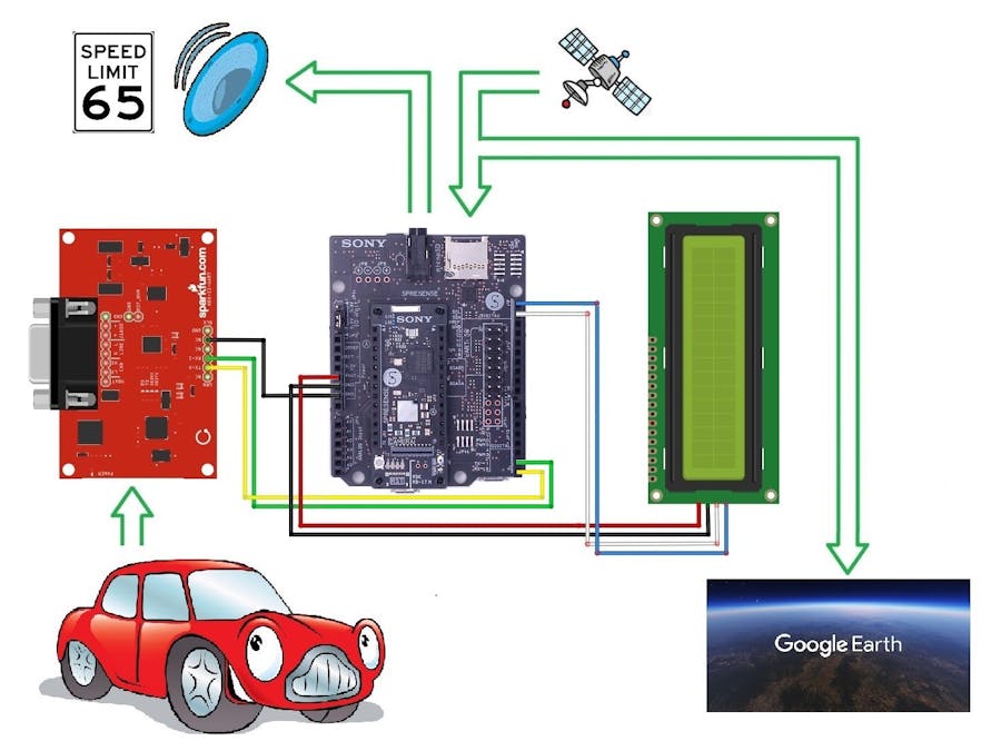
The OBD integration consists of the Sony Spresense board, a SparkFun OBD-II-UART interface board, and a HD44780 2x16 LCD panel with I2C backplate. The functionality presented in this basic version interfaces with the vehicle, receiving Speed and RPMs, and displaying them on the LCD panel.
The Sprenense functionality is provided in four parts: 1) Record vehicle location using GPS coordinated from the on board GNSS receiver, 2) Logs event history (KML files) for visual overlay on Google Earth using on board SD card, 3) Provide audible speed reference from 25-125km/h using the stereo headphone 3.5mm 8Ω audio jack and 4) making use of the 4 main board LEDs as status indicators.
Basic Connection/ReportingWiring It Up
Although, the wiring for an Arduino UNO is listed for reference, wire according to the Spresense guide. Variations with the UNO are called out for additional understanding.
UART Connection
An UNO wiring will require the use of a SoftwareSerial library as the UART pins D0/D1 are shared with the Arduino IDE and cause conflicts. As the Spresense is enhanced with two separate UARTs, the limitations requiring SoftwareSerial library is removed. For the Spresense, D0/D1 can be used for TX/RX which tied to UART2, and the IDE Monitor is tied only to the USB port, which is UART1.
UNO		Spresense	Jumper		OBD-II UART
-			-			NC
D10-RX		D0-RX		Yellow		TX-0
D11-TX		D1-TX		Green		RX-1
-			-			NC
-			-			NC
GND		GND		Black		GND
I2C LCD Connection
The Spresense has multiple I2Cs built in. IC0 is configured with use for pins D14/D15 on the main or extension board. On the UNO analog A4/A5 pins are used to support I2C connections. The wiring for both is as follows:
UNO	Spresense	Jumper		LCD HD44780
GND	GND		Black		GND
5vdc	5vdc		Red		VCC(+5vdc)
A4	D14		White		SDA
A5	D15		Blue		SCL
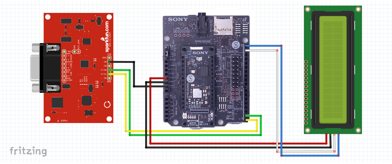
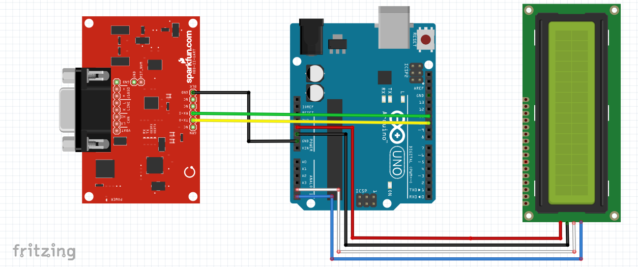
Below are references for both the Arduino UNO, and Sony's Spresense wiring
With the wiring complete, the basics are done and only two parts remain; downloading and applying the attached code, and connecting the OBD-II UART interface to the vehicle. However before we jump to fast, there is more to learn. To start let me cover a bit about the wired integration with the OBD-II and LCD boards.
Integration Use - OBD-II
The interface with the OBD-II breakout board is simple serial communication. There are two parts to the functional dialog which include first, establishing the connection and dialog language to the vehicle. Then second, polling the vehicle for information. These two aspects are based in key standards referred to as follows:
IC ELM327 - RS232 Interpreter, Using AT Commands
Aside from just a wired serial dialog, the communication protocol/language needs to be understood. The ELM327 manages connection between vehicle OBD-II interface and the serial interface through the use of the Hayes command set or "AT" commands. Further general information can be located at this link and examples are as follows:
- ATZ Reset serial connection
- ATE0 Turn serial character echo off
IC MCP2551 – CAN Transceiver
The next layer of communication is with the using the CAN transceiver to pass PID codes, or parameter IDs; these codes are used to request vehicle information. This follows an SAE industry standard J/1979 which defines many standard PIDs. However, manufacturers also define additional PIDs to support specific vehicle characteristics. Example use is as follows:
- 010C is used to receive vehicle engine RPMs in ¼ revs/pm. The value returned is in subsequent two bytes, and is determined by converting the hex to decimal, then dividing by 4.
- Calculation to RPM is based on sending "01 0C", then as an example receiving "XX YY". Then, calculated RPMs is ((XX*256)+YY) / 4
Physical Connection
The OBD-II UART board uses a DB9 to OBD-II connector. The vehicle interface is typically under the driver's side dash. In some makes it can be on the passenger side.
Integration Use - LCD Panel
Exchanging vehicle information is supplied with the OBD-II board. However, you will need to do something with the data. This is where the LCD panel is helpful. Using the panel, has been made quite easy using the LiquidCrystal_I2C library, and it supports many other LCD panels with the I2C backplate. Below are some basic settings and functions used to support and operate the LCD panel
Instantiating the I2C
- LiquidCrystal_I2C lcd(0x27, 16, 2); //Sets the I2C address and dimensions
Operational Command Use
Command     Example                     Meaning
.init()     lcd.init();                 // Initialize LCD Display
.backlight  lcd.backlight();            // Initialize backlight display
.clear      lcd.clear();                // Clear the display
.setCursor  lcd.setCursor(0, 0);        // Set the cursor to col0/row0
.print      lcd.print("Hello world!");  // Print message
To avoid some issues with readability, it is advisable to delay operations for about 50 milliseconds between some operational commands.
When using the board you may have to adjust the rheostat on the backplate to adjust the contrast to see the output. This adjustment will allow you also to see black on white, or white on black lettering
Operational Use
Although the attached code is written for the entire solution, this is a break point for you to consider parring down the code to check the fundamental integration from vehicle to OBD-II interface, to the Spresense, and then out to LCD for reading review.
If assured by testing, or confident to continue, then read on.
Enhanced Programing Using Sony SpresenseAside from minor variations between UNO and Spresense wiring, both platform capabilities exist as noted in the above sections and are rather basic. From this point forward, only Sony's Spresense offer the onboard integrated capabilities, thus leaving the UNO behind.
The enhanced functionality is incorporated in four parts; 1) Record vehicle location using GPS coordinated from the on board GNSS receiver, 2) Log the event history for visualization on Google earth using on board SD card, 3) Provide audible speed reference from 25-125km/h using the stereo headphone 3.5mm 8Ω audio jack, and 4) use of the 4 main board LEDs as status indicators
Record Vehicle Location Using GNSS (Onboard GPS)
- Using the Spresense SDK, you can easily incorporate the GPS code during the looping process to acquire the satellites, pull GNSS data and record coordination location.
- It is recommended that you run the current GPS code to be familiar with its operation and structure before incorporating into this or your own project.
Log the Event History for Visualization on Google Earth
There are two elements to this portion, first is using the onboard SD card and second, to write data in a KML format.
The SD Card: As with the GNSS geolocation program, the SDK has an Audio program which can be used as a base for working the SD card. The difference with this code is you will be writing data rather than reading and the SD library is only as basic library and works adequately for this task. Other SDfat libraries exist for more sophisticated drive/file management, however this project has not extended or tested using other libraries with Spresense.
KML Format: the KML (Keyhole Markup Language) is designed for data overlays and is used in many ways with Google Earth. In this case, a basic "Pathing" method is used and its general structure is located below. The KML file will be in 3 parts; the header, footer, and pathing details. The details consist of the GNSS longitude and latitude, along with a representation of speed to give the path some depth. Reference to KML format and use can be found at the following link.
The solution provided in this project to manage data logging centered on the applied limitations, however further changes can be applied to add better management and operational capability. Below are a few of these distinct limitations.
- The method applied in this example is to start logging once the GNSS data is received, and to stop logging once no more vehicle data is received for more than 20-30 seconds. This approach was chosen as a simple means not requiring additional interfacing/wiring with a switch or button to act as a trigger to start or stop recording.
- The log file name chosen was also limited to the restrictions of the SD library used; a DOS 8.3 format. To make it unique, the file was prefixed with “VL” for Vehicle Log, and the next 6 digits represented day(dd), hour(hh), minute(mm) from GNSS read. Finally, the suffix was “.KML”; entire format is as follows: “VLddhhmm.KML”
Provide Audio Speed Callouts from 25-125km/h
- Using the SDK Audio.ino, a procedure was developed to receive the vehicle speed, and open a MP3 file supporting the audio of that speed value. There are 21 MP3 recording were made of numbers from 25-125; these need to be stored on the SD card. See attached file "AudibleNumbers.zip" for all MP3 files. You will need to unzip these files onto the SD card that will be used for this project.
- With the nature of the asynchronous operation of the audio streaming, and the main program operation, it is necessary to add delays to prevent erroneous returned data that is relied on to close a previously opened the audio file.
- A portable speaker with 3.5mm output jack, and cable is required. Simply connect the Speaker to the Spresense output jack.
Status Reporting
The onboard LEDs on the Spresense main board are used to provide a further visual ques to operational activity, and are represented as follows:
LED	On			Off
0	OBD connected/Live	Timed out
1	GNSS acquiring		GNSS acquired
2	Logging to KML		Logging closed
3	Not Use			Not Used
These LEDs can be programmatically turned on an off by issuing Led_On(x); and Led_Off(x); commands where x is the representative LED number above.
Operation ModesThe following are operation modes defined in the beginning of the program. Each, when defined or not defined, can provide control in a delivered/compiled executable.
- VER_SPRITZER - Not currently used. However, this is intended for making the code portable between different boards.
- VER_MONITORING - If defined, this will send additional debugging messages to the IDE monitor
- VER_AUDIO - If defined, this incorporates the Spresense Audio capability. However, doing so will result in no KML logging. The issue is with opening multiple files using the current SD library. An alternate form of programming can be applied to prevent such issues, but becomes inefficient and is not considered here.
- VER_OBD – Typically left defined as this is core to the general operation. However if not defined, will simulate operation without OBD connection. In either state, remember that VER_AUDIO must be undefined in order to perform logging (The writing of a KML file)
Full Operation Sequence example
This can operate with or without laptop monitoring. Assuming this will be monitored through the Arduino IDE, the following is the sequence for starting and stopping this integration. WARNING: Do not operate a motor vehicle while monitoring or actively engaged with this equipment or software. It is advised to initiate this in a standalone process or in full operation with a second person operating the vehicle while a passenger can monitor progress or events.
Read the below steps carefully so you may be familiar with the steps, timing, and expectations, before actually running/operating.
Ready
- Have the laptop ready with the Arduino IDE and program loaded
- Plug in the Micro-B plug of the USB connector to the Spresense(Do not power on yet)
- Ensure a self-powered speaker is plugged into the Spresense (3.5mm 8Ω audio jack)
- Ensure a formatted Micro SD card is inserted into the Spresense SD slot
- Plug in the OBD cable in to the OBD plug on the vehicle. CAUTION: Since this connection is likely under the dash ensure the cable is properly moved out of the way from any interference with steering, braking, acceleration or other normal vehicle use.
Set
- Plug in the USB connector into the laptop (Serves as the power source)
- Upload the program to the Spresense board(This will clear any existing program and make you are aware of the running code)
- Start the vehicle (This will power the OBD and/or make it available to commutate)
- Plug in the D9 serial connector of the OBD cable into the OBD-II UART (Now everything is connected)
- Switch to the Arduino IDE Monitor
Go!
The following operational events will occur during the life cycle run of this integration
- Once the vehicle is running and the OBD connection is established, the continual polling of vehicle information will be received. The Arduino IDE monitor, LCD, and board lights will provide some guide to what is happening
- During this same process GNSS (GPS) locating will begin. It make take some time for the isolation and triangulation of satellites before actual coordinates are provided; 5-20minutes depending on location or other circumstances. Note: GNSS reception will be poor to non-existent in enclosed places, underground, and perhaps in tunnels.
- As soon as the GNSS information is received, vehicle logging to the SD card will occur, writing the data in KML format; suitable for plotting and reviewing on Google Earth later.
- While driving, and reaching 5km/h increments from 25 to 125km/h, an audible callout of the speed will be heard. While the driver has his hands on the wheel and focus on road conditions, this is very useful for learners, back seat drivers, or the blind.
- To conclude data logging, the OBD cable is to be disconnected from the vehicle for 20-30 seconds to close the log file. Power must still be applied to the Spresense board during this time for proper file closure.
Shutting down
- Before turning off the vehicle, ensure that the vehicle is properly, safely parked and with the parking brake on.
- Unplug the D9 connector of the OBD cable.
- Wait 20-30 seconds before shutting off the vehicle
- Shut off the vehicle
Alternative Sequence/Notes
Once the Spresense is programed, the need for the laptop/Arduino IDE is not necessary, this would eliminate the need for a laptop. However, since power would be provided by the laptop you will have to switch to using the USB connector on the Spresense board and power from the vehicle or other battery source, ensuring proper voltage conversion. Newer vehicles are made with built in USB port for charging cell phones and can be a perfect option. With this alternative (no laptop/IDE) the general steps would be as follows:
- Plug in the OBD cable from the vehicle to the OBD-II UART board. CAUTION: Since this connection is likely under the dash ensure the cable is properly moved out of the way from any interference with steering, braking, acceleration or other normal vehicle use.
- Plug the cable from the vehicle's 5vdc power system to the Spresense main board (Micro-B USB)
- Turn on the vehicle
- See the "Go!" section above
- Shutting down, unplug the D9 connector of the OBD cable.
- Wait 20-30 seconds before shutting off the vehicle
- Shut off the vehicle
If further enhancements are applied, such as adding a physical on/off switch to control enabling and disabling the KML logging, then the process for starting/stopping is not needed. Regardless the key in this version are the following 3 steps to close the file logging:
- Unplug the D9 connector of the OBD cable.
- Wait 20-30 seconds before shutting off the vehicle
- Shut off the vehicle capabilities
Porting code the Sony Spresense is rather easy, there are however some changes that might need to be applied, and some are called out here. Others, can be reference in their online documentation.
Although, I have incorporated using the onboard GPS/GNSS, the SD card, Audio features into this project, the Spresense offers other capabilities that can be further explored including an accelerometer, other audio/speaker control.
For all these features, Spresense provides another angle for discovery, automation, and IoT development. For more information on the Spresense, see the following on Hackster.


_3u05Tpwasz.png?auto=compress%2Cformat&w=40&h=40&fit=fillmax&bg=fff&dpr=2)


Comments