

Hardware components | ||||||
 |
| × | 1 | |||
Software apps and online services | ||||||
 |
| |||||
Hand tools and fabrication machines | ||||||
 |
| |||||
 |
| |||||
Story
Thanks again PCBWay for sponsoring my project. PCBWay You can have your PCB boards produced for 10$. And it provides all kinds of printing and assembly services.
PCBWay: https://www.pcbway.com/
My PCBWay profile: https://www.pcbway.com/project/member/?bmbno=188E1A91-204D-49
PCBWay share project: https://www.pcbway.com/project/shareproject/KeyboradPad_19a59ab6.html
#pcbway #pcb #pcbuild #pcbtoday
Attiny85The aim of the project will be to control the Attiny85 microcontroller using 10 mechanical switches. Mechanical switches will be read by the microcontroller's digital inputs and used to check if each switch has been pressed. According to the number of keys pressed, the LEDs will flash.
Materials you need:
Attiny85 microcontroller
10 mechanical switches
10x 10k ohm resistors
10pcs LEDs
breadboard
jumper cables
Links:
The VCC pin of the Attiny85 microcontroller should be connected to the positive power line of the breadboard.
The GND pin of the Attiny85 microcontroller must be connected to the negative power line of the breadboard.
Mechanical switches must be connected to the Attiny85 microcontroller, each with a digital input pin. Each of the switches must be connected together with a 10k ohm resistor. This ensures a smooth reading.
The anodes of the LEDs must be connected to the digital outputs of the Attiny85 microcontroller. Each of the LEDs must be connected together with a 220 ohm resistor. This helps protect the LEDs.
Programming:
You can write the project with Arduino IDE. This means you can find many resources you can use to program the Attiny85 microcontroller.
Function:
The project contains a set of code blocks that check if mechanical switches are pressed. According to the number of keys pressed, the LEDs will flash. In the project, power consumption is also optimized by using the "sleep" mode, which is one of the energy saving modes of the Attiny85 microcontroller.
All in all, this project is a simple Attiny85 implementation using 10 mechanical switches. A simple code is used in the project to check the status of the switches by flashing the LEDs. This project can be a great example for those new to working with microcontrollers.
first of all, this project is a "10 switch simple LED control project". Flashing of the LEDs is provided by using 10 mechanical switches.
The Attiny85 microcontroller is the heart of this project. The LEDs used in the project are connected to the digital output pins on the Attiny85, along with 220 ohm resistors. The digital input pins are used to read the state of the 10 mechanical switches.
In the code, in the "setup()" function, digital input pins and digital output pins are defined. The "loop()" function reads the status of 10 switches and then determines the number of LEDs that will light up. The states of the LEDs are adjusted according to the number of LEDs that will light up.
The switches used in the project are simple mechanical switches and do not have any functional features. The purpose of this project is to learn to control LEDs using a microcontroller and to practice basic microcontroller programming.
Different variations of this project can be done using different numbers of switches or LEDs. The project can be used for learning purposes as well as for entertainment purposes.
Microcontroller: Attiny85 is one of the series of 8-bit AVR microcontrollers. This microcontroller is a popular choice due to its low power consumption, small size and affordability. Attiny85 has 8 KB memory capacity and 5 digital input/output pins.
LEDs: The LEDs used in this project are standard round 5mm LEDs. The LEDs are programmed to turn on or off in the project. Each LED is connected to a digital output pin along with a 220 ohm resistor.
Keys: In this project, 10 mechanical keys are used. Keys are arranged in accordance with the purposes of the project. Each switch is connected to a digital input pin with a 10 kohm resistor.
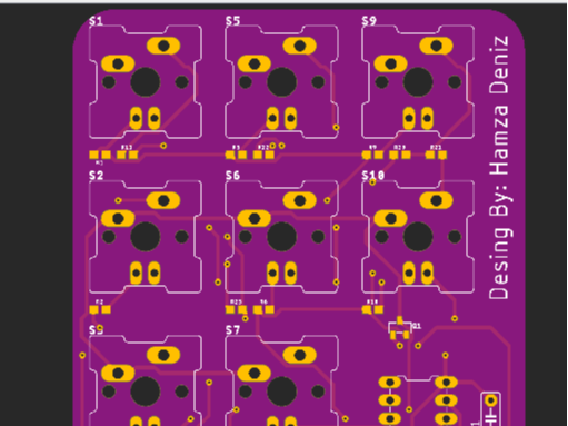
Circuit diagram: The circuit diagram in the project is quite simple. 10 switches are connected to the digital input pins of the Attiny85 microcontroller. The LEDs, along with 220 ohm resistors, are connected to the digital output pins of the microcontroller.
Code: The code used in the project can be written in a development environment such as the Arduino IDE or Atmel Studio. The code defines the digital input pins and digital output pins. Next, the status of each switch is read and the number of LEDs to light is determined.
Application: This project has many different application areas. For example, this project could be a toy, a home automation system, or an industrial control system. By developing this project, you can design more complex systems to be used in many different application areas.
CODE:const int button1 = 0;
const int button2 = 1;
const int button3 = 2;
const int button4 = 3;
const int button5 = 4;
const int button6 = 5;
const int button7 = 6;
const int button8 = 7;
const int button9 = 8;
const int button10 = 9;
const int led1 = 0;
const int led2 = 1;
const int led3 = 2;
const int led4 = 3;
const int led5 = 4;
const int led6 = 5;
const int led7 = 6;
const int led8 = 7;
const int led9 = 8;
const int led10 = 9;
void setup() {
pinMode(button1, INPUT_PULLUP);
pinMode(button2, INPUT_PULLUP);
pinMode(button3, INPUT_PULLUP);
pinMode(button4, INPUT_PULLUP);
pinMode(button5, INPUT_PULLUP);
pinMode(button6, INPUT_PULLUP);
pinMode(button7, INPUT_PULLUP);
pinMode(button8, INPUT_PULLUP);
pinMode(button9, INPUT_PULLUP);
pinMode(button10, INPUT_PULLUP);
pinMode(led1, OUTPUT);
pinMode(led2, OUTPUT);
pinMode(led3, OUTPUT);
pinMode(led4, OUTPUT);
pinMode(led5, OUTPUT);
pinMode(led6, OUTPUT);
pinMode(led7, OUTPUT);
pinMode(led8, OUTPUT);
pinMode(led9, OUTPUT);
pinMode(led10, OUTPUT);
}
void loop() {
int buttonState1 = digitalRead(button1);
int buttonState2 = digitalRead(button2);
int buttonState3 = digitalRead(button3);
int buttonState4 = digitalRead(button4);
int buttonState5 = digitalRead(button5);
int buttonState6 = digitalRead(button6);
int buttonState7 = digitalRead(button7);
int buttonState8 = digitalRead(button8);
int buttonState9 = digitalRead(button9);
int buttonState10 = digitalRead(button10);
int ledCount = 0; // Başlangıçta yanacak LED sayısı
if (buttonState1 == LOW) {
ledCount++;
}
if (buttonState2 == LOW) {
ledCount++;
}
if (buttonState3 == LOW) {
ledCount++;
}
if (buttonState4 == LOW) {
ledCount++;
}
if (buttonState5 == LOW) {
ledCount++;
}
if (buttonState6 == LOW) {
ledCount++;
}
if (buttonState7 == LOW) {
ledCount++;
}
if (buttonState8 == LOW) {
ledCount++;
}
if (buttonState9 == LOW) {
ledCount++;
}
if (buttonState10 == LOW) {
ledCount++;
}
digitalWrite(led1, ledCount > 0);


Comments