


Hardware components | ||||||
_ztBMuBhMHo.jpg?auto=compress%2Cformat&w=48&h=48&fit=fill&bg=ffffff) |
| × | 1 | |||
 |
| × | 1 | |||
 |
| × | 1 | |||
Software apps and online services | ||||||
 |
| |||||
Illuminance is very important. Correct illumination is one of the main factors for a work environment to offer efficient working conditions that do not cause fatigue and discomfort to the employees' vision.
The more an environment or function requires the employee's vision (for example in an electronic workshop, where the handling of very small components is common), the greater the illuminance that the environment will require, as determined by the norm of your country.
In any country, there is a standard for interior illuminance, which specifies the minimum, average, and maximum illuminance for each environment and function or job.
Thus, measuring the illuminance is something very important and essential for the safety and comfort of the employees of a company.
In this article, you will learn how to use Arduino, LCD display, push-buttons, and a BH1750 sensor to measure the illuminance of two environments: an office and an electronic workshop.
In addition, the project will automatically classify the illuminance measured as OK, HIGH, or LOW.
That way, you'll learn:
- How to use the LCD shield with keyboard for Arduino
- How to read the ambient light with the BH1750 sensor
- How to automatically classify the illuminance of two different environments as OK, HIGH or LOW.
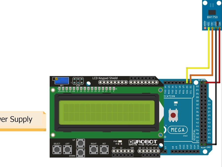
Before we start explaining our project, see the schematic circuit shown in figure 1. We will use an LCD module with Keyboard and use the buttons on the shield keyboard to control the PCBGOGO Illuminance Meter Application.
To facilitate the fitting of the LCD shield with the keyboard on the Arduino, look for the analog inputs (from A0 to A5) and align them with the ones written/indicated on the shield.
The circuit assembly, in practice, will be as shown in figure 2.
The LCD screen displays the brightness value and low light message for an office.
In terms of hardware, this project makes use of:
- 01 x PCBGOGO Printed Circuit Board
- 01 x Arduino Mega 2560 R3
- 01 x LCD shield with keyboard for Arduino
- 01 x module with BH1750 sensor
- 01 x USB cable type A / B for programming and powering the Arduino Mega 2560. If you don't know this USB cable by name, this is the same type of USB cable used in printers (with that square end).
- 01 x 5V / 1A switched DC power supply, for powering the project without the computer (optional)
In general terms, the schematic circuit of the project has three parts: Arduino Mega 2560 R3, a module with a BH1750 sensor, and an LCD shield with a keyboard for Arduino.
See the details of these parts in detail below.
Overview of the Arduino Mega 2560 R3
The Arduino Mega 2560 R3 is one of the largest Arduinos in existence, both in GPIOs (pins) available and in computational resources (RAM memory, Flash memory for programming, processing power, etc.).
Its specifications are:
- Microcontroller: ATMEGA 2560
- Microcontroller Operating Voltage: 5V
- The maximum input voltage of Arduino Mega 2560 R3 (through connector P4): 12V
- Digital Ports: 54 (where 15 can be used as PWM)
- Analog Ports: 16
- The maximum electrical current output of a GPIO (pin): 50mA
- Flash memory: 256kB (8KB of which is used for the bootloader, with 248kB left for programming)
- SRAM memory: 8kB
- EEPROM Memory: 4kB
- ATMEGA 2560 processor clock speed: 16MHz
This Arduino is suitable for those who are doing a more elaborate project, which requires many GPIOs (pins) for the project, as well as those who need a lot of RAM and Flash.
This is the case with the way this article works, due to the LCD shield with keyboard for Arduino using many pins and there is still a need for power and communication for the illuminance sensor.
Figure 3 illustrates the Arduino Mega 2560 R3.
Now I'll present the BH1750 Sensor Module for Arduino.
Overview of the BH1750 sensor module
This module has a BH1750 sensor, which has the functionality of measuring illuminance.
The BH1750 sensor consists of an integrated circuit of small physical dimensions that uses communication via the I²C protocol to communicate with microcontrollers.
This sensor is capable of measuring illuminance in a range from 1 Lux to 65, 535 Lux, and can operate in a temperature range of -40 ° C to + 85 ° C.
Thus, this sensor can be used to measure illuminance in the most varied types of environments.
Figure 4 shows a module containing the BH1750 sensor.
Now, we will see the operation of the Shield LCD 16 x 2 with Keyboard
Overview - Shield LCD with keyboard for Arduino
The LCD shield with keyboard for Arduino consists of a shield that offers:
- A 2-row, 16-column LCD display with backlight
- Five push-buttons, analog readable
- A reset key (to reset the Arduino to which the shield is connected)
- A potentiometer for adjusting the LCD contrast
The shield can be seen in figure 5.
As mentioned, the five keys that can be used for programming (Select, Left, Up, Down, and Right) are read analogously.
That is, each key pressed causes a different voltage level in one of the Arduino's analog inputs (in this case, input A0).
In this way, it is possible to find out which key was pressed by reading the zero channel of the Arduino ADC (analog-to-digital converter).
Programming the Arduino Mega 2560 R3 in the Arduino IDE
The Arduino Mega 2560 R3 can be programmed into the Arduino IDE like any other Arduino.
To do this, select the “Arduino / Genuino Mega or Mega 2560” board in Tools> Board on the Arduino IDE.
Installation of the library for reading the BH1750 sensor
For this project, it is necessary to install the BH1750 sensor library. To do this, follow the procedure below:
- Download the library directly from its official Github repository from the link: https://github.com/claws/BH1750/archive/master.zip. Save the library's.zip file to a location/folder that is easily accessible to you.
- On the Arduino IDE, go to Sketch> Include Library> Add.ZIP Library…
- In the window that opens, go to the location/folder where you saved the library's.zip file and double-click on it.
- The library is installed and ready to use.
You need to be very careful about this and I'll tell you
The BH1750 sensor library requires that the interval between two consecutive illuminance readings be at least 150 milliseconds.
If this is disobeyed, the reading value is not updated (the value of the last reading remains).
Now, I'm going to introduce you to the complete source code for this project.
At this point, everything is ready to implement the project! The source code of the PCBGOGO project can be found below.
The procedure for putting the project into action is the same as with any other Arduino: just copy this source code, paste it into your Arduino IDE, save the Sketch, compile and upload/program the Arduino Mega 2560 R3.
Read the source code comments carefully to fully understand it.
/* Projeto: leitor de lux para dois ambientes distintos (escritório e oficina eletrônica
* Este projeto considera os valores de lunosidade da NBR5413.
*
* Links importantes:
* - Link para biblioteca do sensor de Lux BJ1750: https://github.com/claws/BH1750
*/

#include <LiquidCrystal.h>
#include <Wire.h>
#include <BH1750.h>

/* Definições gerais */
#define NUMERO_MEDICOES_SENSOR_LUX 5

/* Definições - teclas */
#define CANAL_ADC_TECLAS 0
#define TECLA_NENHUMA 0
#define TECLA_LEFT 1
#define TECLA_RIGHT 2
#define TEMPO_DEBOUNCE 200 //ms

/* Definições - display */
#define DISPLAY_NUM_COLUNAS 16
#define DISPLAY_NUM_LINHAS 2
#define TEMPO_MIN_ENTRE_MEDIDAS_SENSOR_LUX 150 //ms
#define DISPLAY_LINHA_EM_BRANCO " "

/* Definições - limites de luminosidade */
#define ESCRITORIO_LIMITE_SUPERIOR 1000 //lux
#define ESCRITORIO_LIMITE_INFERIOR 500 //lux
#define OFICINA_ELETRONICA_LIMITE_SUPERIOR 5000 //lux
#define OFICINA_ELETRONICA_LIMITE_INFERIOR 2000 //lux

/* Objetos e variáveis globais */
BH1750 medidor_lux;
uint16_t lux_medido;
char tecla_lida_primeira_vez = TECLA_NENHUMA;
char tecla_lida_segunda_vez = TECLA_NENHUMA;
char ultima_tecla_lida = TECLA_NENHUMA;
char lcd_linha2[16] = {0};

/* Inicializa objeto do display LCD com
os GPIOs utilizados pelo shield para tal fim */
LiquidCrystal lcd(8, 9, 4, 5, 6, 7);

/* Protótipos de funções */
char leitura_teclado(void);
int media_leituras_sensor_lux(void);
void formata_linha_e_classifica(char * linha_lcd, uint16_t lux_medido, uint16_t limite_superior, uint16_t limite_inferior);

/* Função: le teclas right e left
* Parâmetros: nenhum
* Retorno: tecla lida
*/
char leitura_teclado(void)
{
int leitura_adc = 0;
char tecla_lida = TECLA_NENHUMA;

/* A leitura do teclado no shield LCD + Keypad é feito com base em leitura
analógica. Ou seja, cada tecla pressionada vai provocar um nível de
tensão direfente no ADC (no canal definido por CANAL_ADC_TECLAS), permitindo
assim distinguir entre as teclas presentes.
Este projeto utiliza somente duas das 6 teclas presentes: left e right.
*/

leitura_adc = analogRead(CANAL_ADC_TECLAS);

if (leitura_adc < 50)
{
tecla_lida = TECLA_RIGHT;
}

else

{
if (leitura_adc < 650)
tecla_lida = TECLA_LEFT;
}

return tecla_lida;

}

/* Função: formata linha de LCD com medição (lux) e classificação
* Parâmetros: nenhum
* Retorno: tecla lida
*/

void formata_linha_e_classifica(char * linha_lcd, uint16_t lux_medido, uint16_t limite_superior, uint16_t limite_inferior)
{

memset(linha_lcd, ' ', DISPLAY_NUM_COLUNAS);

if ( (lux_medido >= limite_inferior) && (lux_medido <= limite_superior) )
sprintf(linha_lcd, "%d lx - OK", lux_medido);
else

{
if (lux_medido > limite_superior)
sprintf(linha_lcd, "%d lx - ALTO", lux_medido);
if (lux_medido < limite_inferior)
sprintf(linha_lcd, "%d lx - BAIXO", lux_medido);
}

}

int media_leituras_sensor_lux(void)
{

int i;
long int soma_lux = 0;
long int media = 0;
for (i=0; i<NUMERO_MEDICOES_SENSOR_LUX; i++)
{
soma_lux = soma_lux + medidor_lux.readLightLevel();
delay(TEMPO_MIN_ENTRE_MEDIDAS_SENSOR_LUX);
}

media = soma_lux / NUMERO_MEDICOES_SENSOR_LUX;
return (int)media;
}

void setup()
{

/* Configura e escreve mensagem inicial no display LCD */
lcd.begin(DISPLAY_NUM_COLUNAS, DISPLAY_NUM_LINHAS);
lcd.setCursor(0,0);
lcd.print(" Escolha o");
lcd.setCursor(0,1);
lcd.print("ambiente (L/R)");
/* Inicializa o BH1750 (medidor de lux) */

Wire.begin();

medidor_lux.begin();
}

void loop()
{

int media_lux;

/* Faz leitura do teclado com debounce */
tecla_lida_primeira_vez = leitura_teclado();

if (tecla_lida_primeira_vez != TECLA_NENHUMA)
{
/* confirma a leitura */
delay(TEMPO_DEBOUNCE);
tecla_lida_segunda_vez = leitura_teclado();

if (tecla_lida_primeira_vez == tecla_lida_segunda_vez)
{
/* Tecla confirmada */
ultima_tecla_lida = tecla_lida_primeira_vez;
lcd.clear();
}

}

/* Se houve alguma tecla lida, executa a ação correspondente */
switch (ultima_tecla_lida)
{
case TECLA_LEFT:
lcd.setCursor(0,0);
lcd.print("Escritorio");
media_lux = media_leituras_sensor_lux();
formata_linha_e_classifica(lcd_linha2,
media_lux,
ESCRITORIO_LIMITE_SUPERIOR,
ESCRITORIO_LIMITE_INFERIOR);
lcd.setCursor(0,1);
lcd.print(DISPLAY_LINHA_EM_BRANCO);
lcd.setCursor(0,1);
lcd.print(lcd_linha2);
break;
case TECLA_RIGHT:
lcd.setCursor(0,0);
lcd.print("Ofic. eletronica");
media_lux = media_leituras_sensor_lux();
formata_linha_e_classifica(lcd_linha2,
media_lux,
OFICINA_ELETRONICA_LIMITE_SUPERIOR,
OFICINA_ELETRONICA_LIMITE_INFERIOR);
lcd.setCursor(0,1);
lcd.print(DISPLAY_LINHA_EM_BRANCO);
lcd.setCursor(0,1);
lcd.print(lcd_linha2);
break;
default:
break;
}

}
Now, we will see the complete functioning of this project.
Step by step operation of the Project
After compiling and uploading the program to the Arduino Mega 2560 R3, the LCD will display a message for the user to select the desired environment. See the figure below.
The LCD displays the message "Choose the environment" in Portuguese.
The user can press 2 keys: the LEFT key and the Right key. If he presses the LEFT key, the system will measure the brightness for the office.
Check the luminance measurement standards in your country and change the values for your region.
The result is shown in the figure below.
In the figure above, the system shows the name of the location on the first line of the display and on the second line, it shows the light level: low, Ok or high.
In this image, the brightness level is indicated as low.
If the user presses the RIGHT key, the system will measure the luminosity for an electronics laboratory.
Observe the measurement result in the Figure below.
Now, we at Robô Lúdico and PCBGOGO will leave an electronic board for you to set up your own project.
PCBGOGO Printed Circuit BoardWe developed a card with a different structure, as many people do not have the Shield LCD with Keypad.
We implemented a PCBGOGO Printed Circuit Board with LCD input with I2C and 4 buttons to create a menu.
In addition, you will use an Arduino Nano. It is smaller than MEGA and can perform the same functions.
Next I am presenting the 3D model of the printed circuit board developed at PCBGOGO and Escola Robô Lúdico.
Now, see how the electronic schematic of the project works in the following figure.
From this schematic was developed the PCBGOGO Printed Circuit presented below.
You can download the board files from this link: Download PCBGOGO Printed Circuit Board.
ConclusionFinally, we have reached the end of our project.
This project can be changed for any type of environment. Always check your country's luminance standards and adapt the values based on the locations to be measured.
In addition, you can use the board and develop it with PCBGOGO PCB Factory. This board can be used in this project and is adaptable for any other type of project that uses a maximum of 4 buttons and an I2C LCD display.
Download the files now and mount your card with PCBGOGO.


Comments