


Hardware components | ||||||
 |
| × | 1 | |||
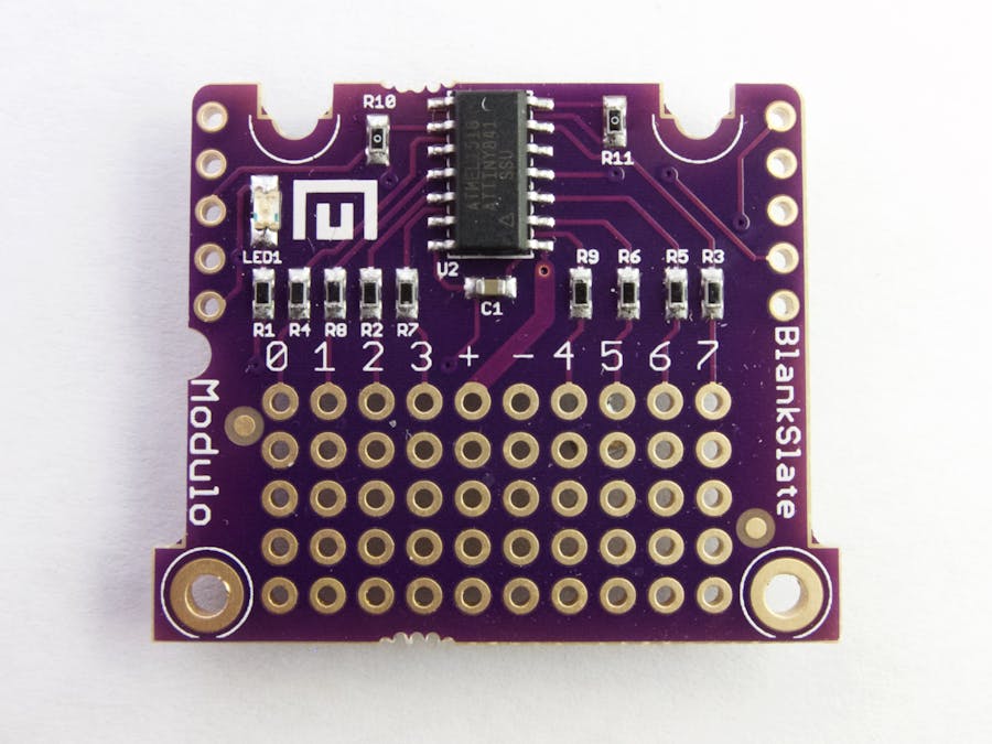
Modulos communicate with the controller over a shared bus (based on the I2C protocol) which allows them to be connected in any configuration. The Blank Slate Modulo connects to that bus and provides a perf board area with 8 general purpose I/O pins, power, and ground.
To build your own Modulo with the Blank Slate, you'll connect your components to these I/O pins and use the Blank Slate API in Arduino, Particle or Python to control your circuit.
Power SupplyThe Blank Slate can operate at either 3.3V or 5V. You can select the operating voltage by soldering or removing the solder from the small solder jump on the back of the Blank Slate.
This jumper will control the voltage of both the I/O pins and the positive power supply pin, marked "+".
In 3.3V mode, your circuit can use up to 150mA. In 5V mode, the maximum current will depend on the power supply you're using.
I/O PinsThe Blank Slate has 8 I/O Pins. Each pin is protected with a 150 Ohm resistor which protects it from damage and makes it easier to power things like LEDs. I/O pins can be used as digital inputs, digital ouputs, analog inputs, or pulse-width modulation outputs.
Blank Slate APIIf you haven't used Modulo before, first go check out the getting started tutorial. The examples below using the Arduino/Particle API, but the Python API is nearly the same.
You'll first need to declare a BlankSlate object:
BlankSlateModulo blankSlate;
If you want to use a specific Blank Slate, you can provide its ID:
BlankSlateModulo blankSlate(12345);
By default, I/O pins are configured as inputs. To read from a specific I/O pin call the getDigitalInput method and provide the pin number. If the pin was previously configured as an output, it will be switched to input automatically.
bool switchPressed = blankSlate.getDigitalInput(2);
You can also read all 8 I/O pins simultaneously. Each bit in the returned value is the state of a different pin. This method will not automatically switch the pin directions.
uint8_t allPins = blankSlate.getDigitalInputs();
If an input pin is disconnected, the result of reading it is undefined. (the value may randomly switch between 0 and 1). You can enable a pull-up on an I/O pin (or set of I/O pins) which is equivalent to connecting a resistor between the I/O pin and +. Then a disconnected input will always read as 1.
blankSlate.setPullup(2, true); // Enable the pullup on pin 2
blankSlate.setPullups(0xFF); // Enable pullups on all pins
You can also read the analog voltage of a pin.
float analogValue = blankSlate.getAnalogInput(2); // Read pin 2 as an analog input
The analogValue will be between 0.0 and 1.0. A value of 1.0 means that the voltage on the specified pin is the same as the + pin.
Digital OutputsI/O pins can also be used as outputs. Calling setDigitalOutput will switch a pin to output mode and set its value.
// Configure pin 2 as an output and turn it on
blankSlate.setDigitalOutput(2, true);
You can also switch a pin back to input mode
blankSlate.setDirection(2, false); // Set pin 2 to input mode
You can also work with all 8 pins as outputs simultaneously. For instance, to configure pins 0 and 2 as outputs and set their values to 1, you can do this:
uint8_t pins = 0b00000101; // Pins 0 and 2
blankSlate.setDirections(pins);
blankSlate.setOutputs(pins);
setOutputs() will not affect any pin that is not configured as an output.
Pulse Width ModulationPins can also be configured as pulse width modulation outputs. This means that the pin will rapidly cycle on and off, with a configurable percentage of time on. PWM is useful for approximating an analog output (for instance, to dim an LED)
The first four I/O pins (0-3) have hardware PWM support, which means that the PWM signal will be very clean, accurate, and free of jitter. The remaining four I/O pins have only software PWM support. While still good enough for many applications, the signal generated by Software PWM may have some jitter and a lower accuracy.
You can configure a pin to use PWM mode and set its value (a percentage of time on, between 0 and 1) using the setPWMValue method.
blankSlate.setPWMValue(2, .25); // Set Pin 2 to PWM Mode. On 25% of the time.
You can also set the PWM Frequency of a specific pin. Pin 0 and 2 share a PWM frequency, and pins 1 and 3 share a PWM frequency. All other pins can have their frequency set independently.
blankSlate.setPWMFrequency(2, 100); // Set pin 2's PWM Frequency to 100 Hz


Comments