


Hardware components | ||||||
 |
| × | 1 | |||
Software apps and online services | ||||||
 |
| |||||
After learning about DC Motor Speed Control and Steering a Three Wheel Robot Carusing the green board designed by Prof. Dan Block from the University of Illinois at Urbana-Champaign, I had the idea of expanding upon the basics of that and allow for greater control over the robot car through the use of the eQEP peripheral of the TMS320F28379D processor and a few additional algorithms.
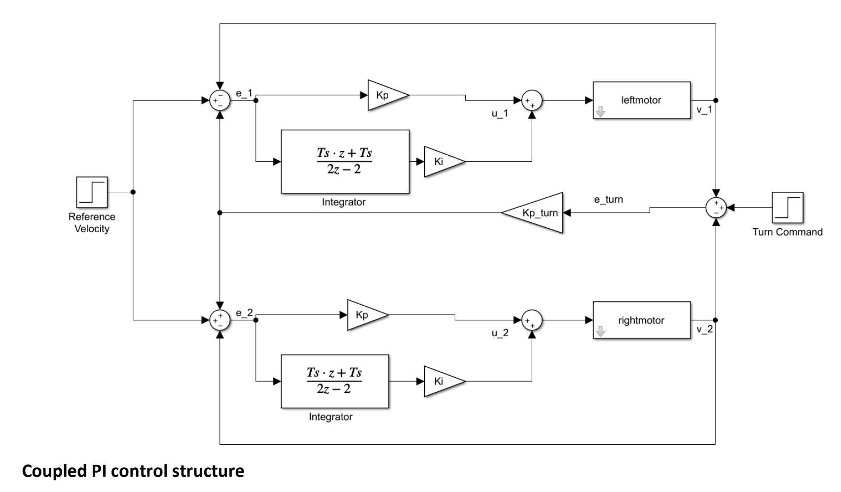
Building up from existing code that uses the DC motor’s magnetic encoder to sense the angle through combining gear ratio with magnetic pulses collected by the quadrature count mode, we are able to effectively detect and control the distance traveled, and consequently, the speed of both wheels. Implementing a coupled PI controller introduced us to two variables, Vref and turn, which namely, controls the speed of both wheels and controls the amount by which one motor’s speed exceeds the other, respectively.
But those are obviously not enough to generate a set of coordinates for the position of the robot car as we still need to take angles into account. With the help of NXTway-GS Model-Based Design and its Two-Wheeled Inverted Pendulum Model, a set of motion equations (shown below) is employed to calculate the angle the car is facing as well as integrating distance over time to obtain the instantaneous xy-position.
From there, a gradient descent algorithm called xy_control written by Prof. Dan Block in his Mechatronics course is implemented with the simple logic of giving a robot’s current position, and a desired position (a local minimum) and it will take small steps towards the desired position. The function itself also calculates the differences in distance between the current and desired position, the tan-1() of that difference which gives us the angle the car needs to face, as well as whether or not the car has reached a certain radius around the destination to stop or slow down. Both Vref and turn are passed by reference into the function and then their updated values are applied into the motor-controlling setEPWM6A/B() functions to activate that change. The car will turn to the angle of the destination at first, then travel in a straight line towards the desired coordinates.
The code is then put to test on the robot car by traversing through various shapes on the ground (video shown below). After setting x and y desired as 2 arrays of coordinates which resemble certain shapes (triangle, square, etc.), the robot car is set to iterate through these points and positions so that it keeps going around and around. Always starting at the origin (0,0) on the x-y plane of a cartesian coordinate system, the robot car can be easily and simply controlled by giving it any sets of coordinates in any quadrants. And it will be able to go through them 1-by-1 with this algorithm.
Many possible applications can be explored with this design, especially regarding path-planning of the robot car. With the help of a coordinate system, the steering of wheels is opened up to greater extent as it no longer has the constraints of the car facing one direction or the many hardships of turning and stopping. This algorithm would also easily allow for navigation through certain paths with given coordinates or perhaps the help of a sensor. While problems like slippage of tires cannot easily be avoided, one possible improvement to increase the accuracy of the desired position would be to take more precise measurements of values like the width of the car, the radius of the wheel, and the unit conversion between radians and feet, which are all crucial parts that contribute to the car arriving at the exact point.


Comments