


Hardware components | ||||||
_wzec989qrF.jpg?auto=compress%2Cformat&w=48&h=48&fit=fill&bg=ffffff) |
| × | 1 | |||
| × | 1 | ||||
.png?auto=compress%2Cformat&w=48&h=48&fit=fill&bg=ffffff) |
| × | 2 | |||
 |
| × | 1 | |||
| × | 1 | ||||
| × | 1 | ||||
| × | 1 | ||||
| × | 1 | ||||
Software apps and online services | ||||||
 |
| |||||
This project is an Android app to control my sail boat. It makes it possible for me to control my deck, navigation, and cabin lights, and to turn on/off the heater with thermostat function. Feedback to Android app with confirmation and outside temperature readings, inside temperature/humidity readings and also battery voltage. It also has a geo-fence alarm which sends a message to my phone if the boat is moved more than 100 (or app settings) meters from it's mooring.
I am currently testing the controller in my boat. I'm not quite finished connecting all cables from the relays, but as you can see on the video some functions are up and running.
The project started when I wanted to be able to control the "Deck Flood" light on my sailboat with a remote control. I live in Norway, and as winter was approaching, it was getting dark and difficult to see the path I have to walk back up from my boat at late afternoon.
Note: As you probably see already, my English is not perfect, hope you understand what I'm writing anyway.
This is my first real build, first large code and also first app build, so there is probably a lot in code and app I could have done easier. But with little experience (I have previously only been trying out some standard example projects on an Arduino Uno) I`m satisfied with it working. I have little to no programming experience, but saw early the possibility to combine and make changes to other sketches that people have made and shared, making them fit to my project. So why not try to make a remote by using an Arduino?
As an beginner I set the difficulties for this project as intermediate, my experience is that challenges in project is to keep control over all functions and to get an good overview. There has been a lot of copy/paste when building code and this makes it a bit messy, but I will try to clean up code, so functions/code are easier to understand.
Build:At first I played around with the Arduino Uno with a Bluefruit shield and a relay card, also starting to make an app using AppInventor 2. I soon found out that this project would be much better if it used a communication system that was not limited to distance.
So I ditched the Bluetooth and upgraded the project by getting an Arduino Mega and adding a Fona 808 GSM Shield. I chose the Mega simply to get some more digital outputs, making it possible to also get a second relay card. With the Fona 808 came also GPS functions, so a Geo-fence alarm and tracking became possible. I also added a temperature sensor for outside readings and an temperature/humidity sensor for inside the boat.
This is first time posting, and I`m not into making sketches in Fritzing so I will try to describe how I built the hardware here:
Started off with Arduino Mega complete with headers:
To get the Adafruit Fona 808 shield to communicate with the Mega I had to find other pins to use for RX/TX serial communication. The shield worked just fine on my Arduino Uno, but I guess not working on Mega has to do with that Mega has multiple serial communication possibilities. Please don`t hesitate to arrest me if I`m wrong, I`m as said an newbie :-). Anyway I searched around and found that pin 10 & 11 could be used and works fine. Therefore I removed the male header pins from RX/TX connections on the Fona 808 shield (pin 2 & 3), and soldered wires on top of the shield from Pin 2 (original RX) to pin 10 & from Pin 3 (original TX) to pin 11.
Then the Adafruit Fona 808 Shield with male headers are ready to be stacked on top of the Mega and you can mount the battery, GPS antenna and the GSM antenna.
You also need an 2G mini SIM card to get Fona working. According to Adafruit not all networks support this anymore, you can red more about this here:
https://www.adafruit.com/products/2636
I had no problem with my network company in Norway, I called them to ask and they said that 2G would be supported on their network for several years to come. I have what we call an "cash card", it is quite cheep to by and has no monthly fee, just transfer money to card when empty... Also my telephone company allows me to add this card to what they call "free family" witch makes calling & sms between this sim card and my phone free.... This is also main reason for using SMS communication between app & Fona instead of GPRS data.
Well, now would be a good time to start testing the boards with examples in the Fona Library to make sure everything works. Remember to change RX/TX pins in the test codes to pin 10 & 11. You're probably also wondering if you need the battery for this, the answer is YES. Fona 808 Shield wont work without it, I think this has to do with peak power consumption during operation.
Now its time to get the boards ready for 12 Volt power.
The Arduino Mega and Fona 808 Shield needs 5 Volt, and my boat, like others have an 12 Volt electrical system. I found this product at the Adafruit webshop and it works fine. I cut off the connector plug, and soldered wires to Fona 808 Shields connectors - Black wire/Negative to "Gnd" and red wire/positive to "Vin"
Before connecting 12 Volt to project, prepare resistors for battery status and voltmeter function.
Connect "DC IN +/-" to +/- at the 12 Volt side of the converter, I used an 100K Ohms for R1 and an 22K for R2. Connect "Analog In" to pin A10.
Now, the relay cards:
I used two 5V 8 channel Relay cards like this one, it has negative & positive pin (Gnd/Vcc) for power you`ll need to connect to Mega/Fona, also connect first relay card`s channel 1-8 to Mega Pin 22-29, and second relay card`s channel 9-16 to Mega Pin 30-37.
I had some issues in the beginning where all relay outputs went "high" / active when code sent " LOW" signal. The relay`s connections makes it possible to use these relays in this way, but this would draw more power when not in use, so I changed therefore code so that when code says output is LOW, Relay goes active. This can be confusing when trying to understand this part of code...
Waterproof Sensor for outside next:
This sensor requires an 4, 7K resistor between Vcc & Data wire, I soldered this to the connector socket showing at next picture. Sensors positive and negative wires got +5 Volt & Ground, I connected the data wire to Mega`s Pin 52.
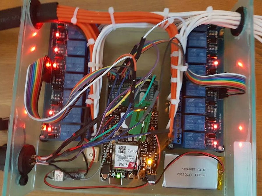
I soldered longer cables to sensors to be able to place sensors where I want them, as you see from project image I also added an connector plug so its possible to remove controller-unit without having to pull cables all over boat. I used an 5 pin connector plug for both sensor cables, so positive & negative where soldered to same connector pin.
Inside Temperature/humidity sensor:
This picture shows the sensor I used, this has an pull-up resistor already mounted on print card. So I just connected positive & negative to +5V & Ground, Data was connected to Mega`s Pin 53.
Then I mounted a lot of wires...
Added an fusebox for 12V power from Battery to Relays and unit. I had this 6-fuses box laying around so I just connected Relay 1-4 to first fuse 5-8 to next and so on... I guess most of you will dislike Relay output connectors at right in picture but I don`t have an label maker yet to mark cables with so this helps me keep them in an order until mounting in boat...
Well, there will always be some issues I guess...
After attaching wires for the most accessible lights in boat I tried out some functions and I found that when I set some of the lights active using app, the control panel in boat gets powered up. In other words boats electric system is behaving like I turned main power switch on, witch set power to lights around the boat if light switch in boat are on. Speaking for my own this is often an issue since I often like to keep lights in boat on until I switch off the main power.
I have an electronic control panel in my boat looking like this:
There is on/off buttons on front, and the backside looks something like this. The outputs from this system is an kind of triac or mosfet transistor and I guess I should be more careful with my connections before trying out my app/controller. But when you`re saying is that "Learning by doing" is for pussies, "Learning by failing" is for men, what else to do than try...
Anyway, only issue is that panel is powering up, so this could only mean that the power I`m adding after panel finds an way through the components on the panel to do so. Therefore I added some powerful diodes (20A) to my connections:
So I connect the power from the display in boat to this diode (top male connector) and connect power from my boat controller relays after the diode (to cable with male connector) and of course output to the light/component to the female connector. And it works perfectly. The diodes keeps power from finding an way through panel. I can also add that one output is controlled by an relay, and since an relay completely breaks power connection when not active this was not necessarily to add on this output.
All Lights in my boat are now connected and controllable from app/controller, and also working as usual when using boat as normal...
Still have to connect the heater...........
App/Controller Functions:
- Heater:
App selection - On:
SMS activates Relay 1 (main power), thermostat functions in code will activate Relay 2 (burner).
Turns on/off my Eberspacher Airtronic Heater with thermostat function. Heater is controlled by to relays, Relay 1 for main power and Relay 2 to activate the burner. Heater original functions lets heater-fan blow for a while after you turned heater off, this to let heater cool down. Code therefore has an delay for main power Relay to maintain this cool down function. Thermostat function lets you set an preferred temperature in app settings, and stops then burner when temperature is achieved. This has also an delay function to prevent burner to start and stop rapidly, code is forcing burner to be active for at least 2 minutes before switching off.
App selection - Off:
SMS deactivates Relay 2 (burner), delay function will deactivate Relay 1 (main power).
- Navigation Lights By Sail:
App selection - On:
SMS activates Relay 3 & 4, app will also deactivate relays 5 & 6.
Navigation lights buttons on the control panel in my boat (Bavaria 32 Cruiser - 2013) has separate buttons/actions for bow lantern (combination red/green) and the stern lantern (white). The connections from Relay to lanterns would "shortcut" these two original outputs making them as one, so to be sure to keep original functions in boat I split this output into Relay 3 & 4.
App selection Off:
SMS deactivates Relay 3 & 4.
- Navigation Lights By Engine:
App selection - On:
SMS activates Relay 3, 4 & 5, will also deactivate relay 6.
The android App will activate the same relays used for NavigathionLights By Sail, but also Relay 5 witch is connected to Mast Head Light (white).
App selection Off:
SMS deactivates Relay 3, 4 & 5.
- Navigation Lights when Moored:
App selection - On:
SMS activates Relay 6, will also deactivate relay 3, 4 & 5.
Relay 6 will be active, wich is connected to Top Lanthern (white).
App selection - Off:
SMS deactivates Relay 6.
- Deck Flow Light:
App selection - On:
SMS activates Relay 7.
App selection - Off:
SMS deactivates Relay 7.
- Cockpit Light:
App selection - On:
SMS activates Relay 8.
App selection - Off:
SMS deactivates Relay 8.
- Aft Cabin Light:
App selection - On:
SMS activates Relay 9.
App selection - Off:
SMS deactivates Relay 9.
- Main Cabin Light:
App selection - On:
SMS activates Relay 10.
App selection - Off:
SMS deactivates Relay 10.
- Main Cabin Light Port:
App selection - On:
SMS activates Relay 11.
App selection - Off:
SMS deactivates Relay 11.
- Main Cabin Light Starboard:
App selection - On:
SMS activates Relay 12.
App selection - Off:
SMS deactivates Relay 12.
- Bathoom Light:
App selection - On:
SMS activates Relay 13.
App selection - Off:
SMS deactivates Relay 13.
- Bow CabinLight:
App selection - On:
SMS activates Relay 14.
App selection - Off:
SMS deactivates Relay 14.
- Extra Function 1:
App selection - On:
SMS activates Relay 15.
App selection - Off:
SMS deactivates Relay 15.
- Extra Function 2:
App selection - On:
SMS activates Relay 16.
App selection - Off:
SMS deactivates Relay 16.
App GeoFence Alarm FunctionsArduino code is continuously reading GPS coordinates for boats location. An button in the android App lets you "refresh" boat location coordinates saved in app. App also has button to open google maps and view location on a map.
App has an "Save Moored Location" button that when pressed sends an message to Arduino code to "save" boats coordinates as "Moored coordinates" (or as in code called "initial coordinates"). App settings also lets you specify how far (in meters) you allow boat to move before activating alarm. I have chosen to have alarm silent, and just send an SMS message. The code has build in alarm outputs if you prefer sound/light alarm on board.
Geofence function is adapted from this geofence project build at Adafruits learning system:
https://learn.adafruit.com/geofencing-with-the-fona-808-and-adafruit-io/how-to-go-further?view=all
Screen shots
I don't have the app ready for sharing, but will share when everything is ready. Some app screenshots from my phone:

Comments