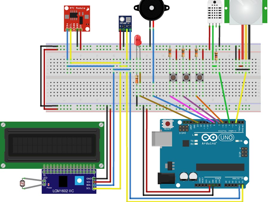
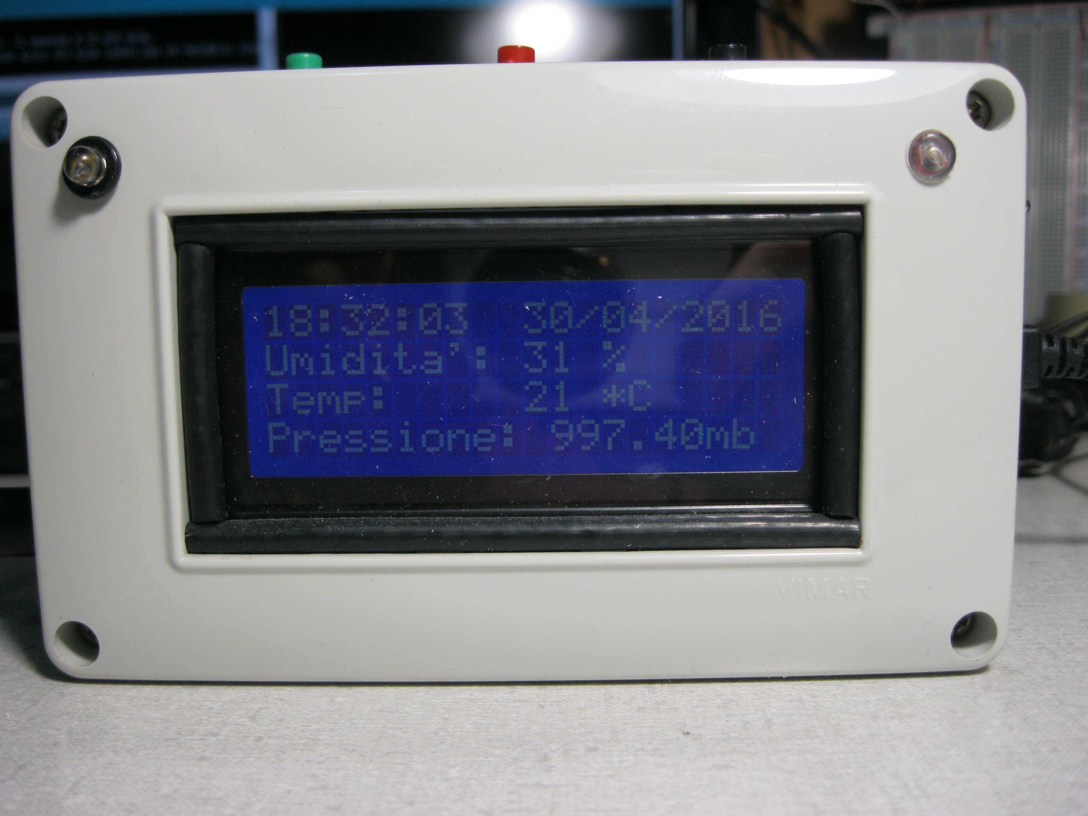
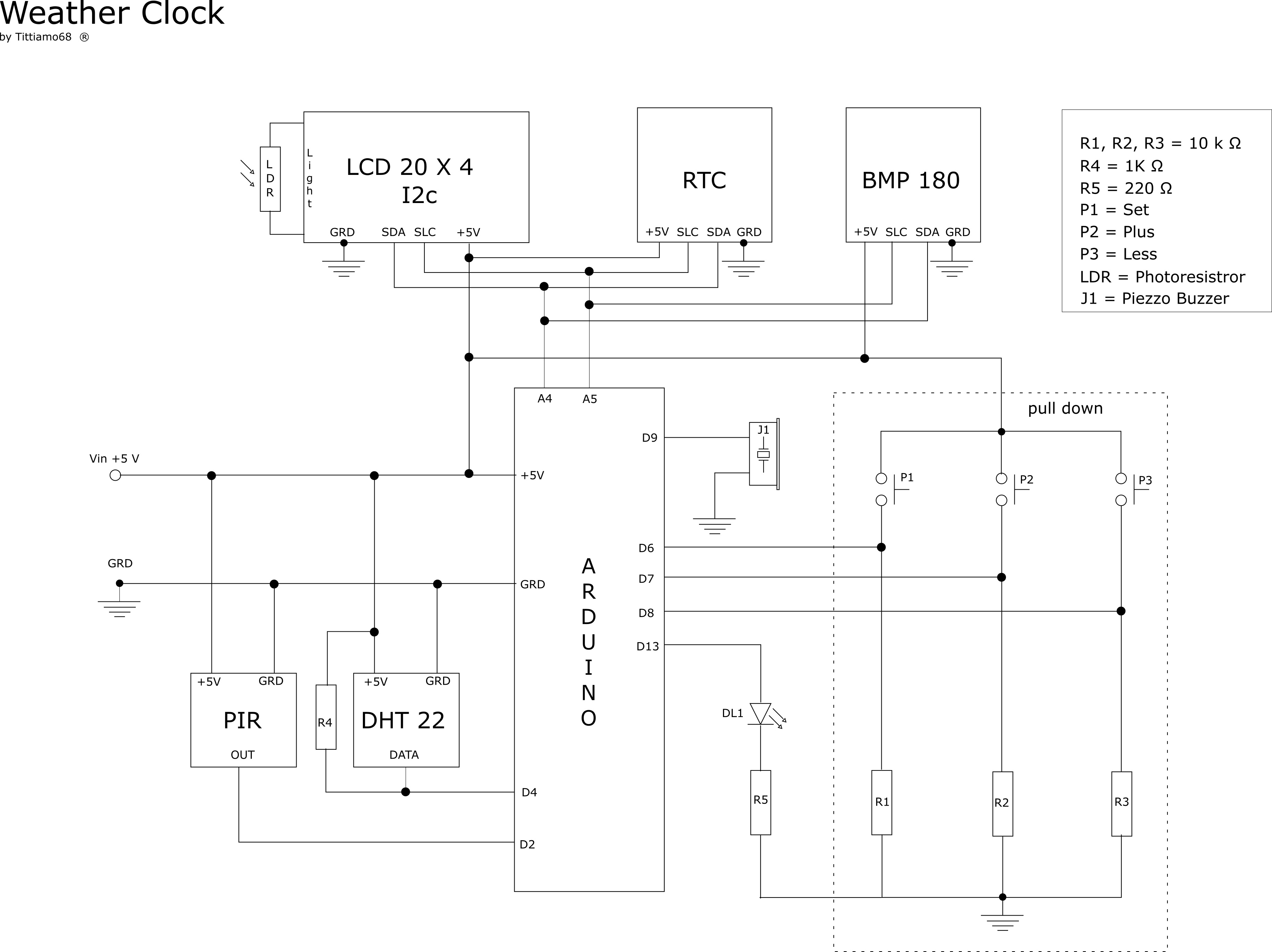
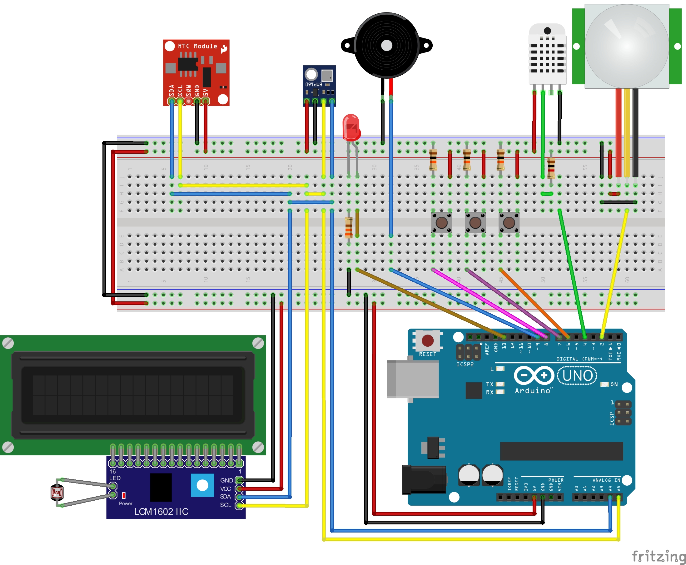
In my workshop I wanted a clock that, in addition to the hours and the date, also displayed the ambient conditions. The work can be done easily with just Arduino, an RTC, a DHT22 and BMP180.
Protocol I2cThe DISPLAY, RTC and BMP180 communicate with Arduino through the I2C protocol and the library wire. All three elements must be connected in parallel to the respective SDA and SLC contacts that correspond to the Arduino pins A4 and A5.
To facilitate the work, and not to confuse the contacts I used the wires with the same colors. The RTC module is a "clock" that, by communicating with Arduino, counts the real time (hour, minute, second, day, month and year). The RTC is supplied by a buffer battery that, when the power is off, continues to calculate the passage of time. The BMP180 Module (Barometric Pressure / Temperature / Altitude Sensor) is a high-performance sensor that provides temperature, barometric pressure and altitude.
Libraries: RTC, DHT, LiquidCrystal_I2C, SFE_BMP180
Display and Photoresistance
The display is very bright. I want it such that when the room is dark, it decreases the brightness.
The I2C module for the display allows you to adjust the contrast and the jumper can turn off the backlight LED. But if we put a photoresistor (provided by the Arduino starter kit) in place of the jumper, with the increase of the light, its resistance decreases, and as a result increases the brightness of the display. Otherwise, while in low light conditions, the resistance is very high and the brightness decreases.
ButtonsThe buttons are used to adjust the time, since the RTC has a margin of error of one minute per month. It should to be constructed a small Pull Down circuit for each button.
The Arduino pins involved in this feature are:
AlarmMy laboratory is located in the basement; and when I'm working, I do not know if someone comes to visit me, so I thought about adding an alarm with a PIR sensor, an LED and a BUZZER.
- The PIR sensor needs to be powered at 5 volts supplied by Arduino and connected to pin 2.
- The LED is connected to pin 13.
For the construction of the box, check this tutorial.
You have been warned!
When you want to visit me… warn me!


_ztBMuBhMHo.jpg?auto=compress%2Cformat&w=48&h=48&fit=fill&bg=ffffff)


_3u05Tpwasz.png?auto=compress%2Cformat&w=40&h=40&fit=fillmax&bg=fff&dpr=2)
Comments