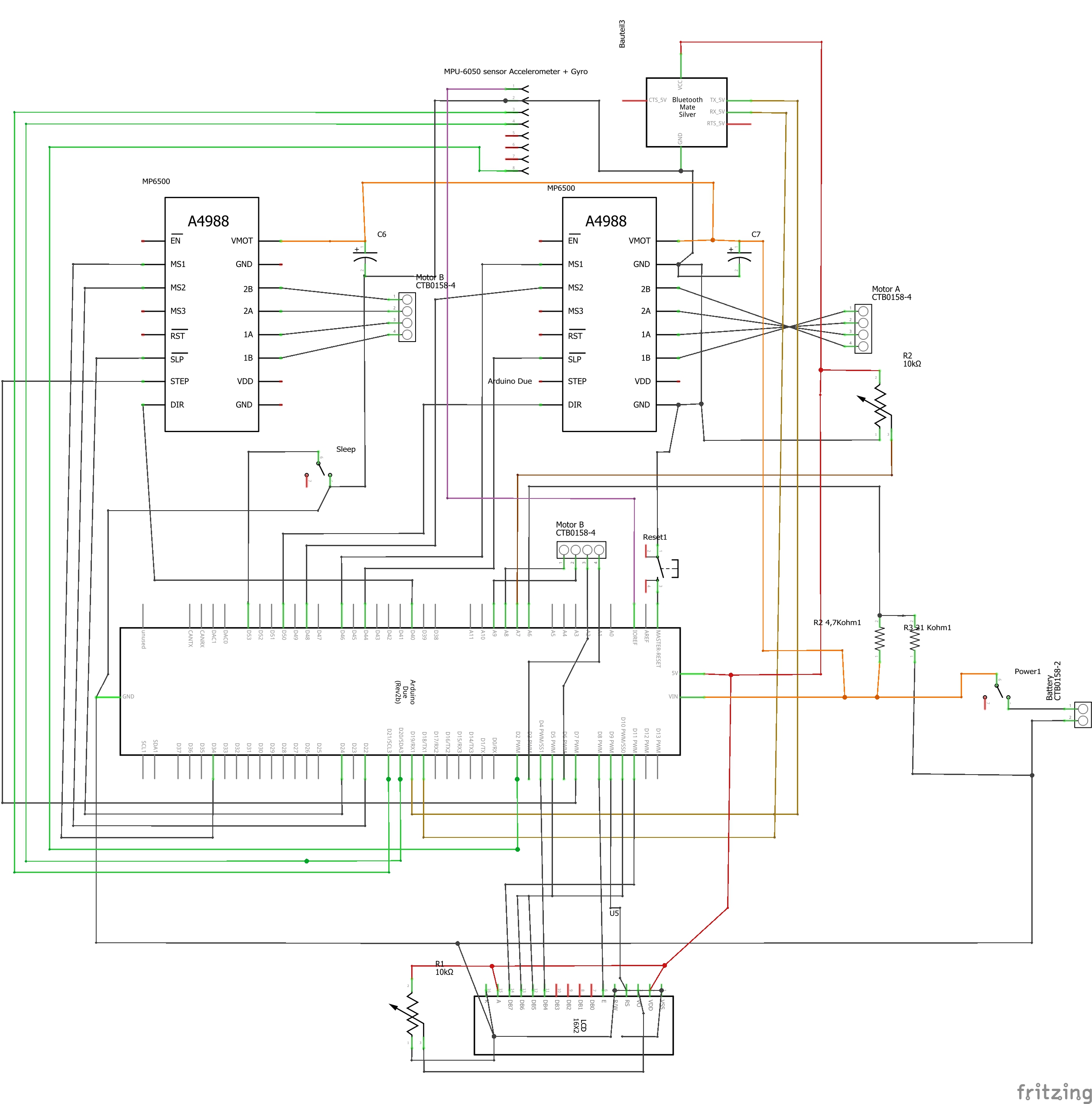
RolfK
Published © GPL3+

two wheeled self balancing robot with stepper motor.

Robot wirth stepper motor via microstepping, digital motion processing, auto tuning, cascaded PID controller and now with Joy Stick Control.

AdvancedWork in progress34,199
two wheeled self balancing robot with stepper motor.

Things used in this project

Hardware components

Arduino Due
Arduino Due
×1
SparkFun Triple Axis Accelerometer and Gyro Breakout - MPU-6050
The InvenSense MPU-6050 sensor contains a MEMS accelerometer and a MEMS gyro in a single chip, with Digital Motion Processing Unit
×1
MP6500 Stepper Motor Driver Carrier
The MP6500 offers up to 1/8-step microstepping and can deliver up to approximately 1.5 A per phase.
×2
RGB Backlight LCD - 16x2
Adafruit RGB Backlight LCD - 16x2
×1
HC-05 Bluetooth Module
×1
NEMA 17 Stepper Motor
OpenBuilds NEMA 17 Stepper Motor
×2
7.4V 2S 3300mAh 35C Li-Polymer Lipo
http://www.floureon.com/product-g_335.html
×1
Joystick Shield
Back to a smaller size, version 1A of Funduino Arduino joystick shield has the same size of the Sparkfun shield but with more features. It includes Bluetooth and nRF2401 RF interfaces.
×1
Arduino Mega 2560
Arduino Mega 2560
used for the joy stick shield
×1

Story

Read more

Schematics

SB Robot

Code

SBRobotDueDP6500_NewPWM_55.ino

C/C++
/* Self balancing Robot via Stepper Motor with microstepping and Digital Motion Processing
    Auto Tuning via Twiddle Algorithmus
    cascaded PID Controller for Motor and for Position
    Task Dispatcher (function handler) via Interrupt
    PWM Controller

    written by : Rolf Kurth in 2019
    rolf.kurth@cron-consulting.de

    The robot consists of the main sketch and the following classes/includes:
    -PidControl
    -Battery
    -DuePWMmod
    -DueTimer
    -Twiddle
    -Motor
    -Vehicle
    -MyMPU
    and the following includes:
    -Config
    -LCD
    -PidParameter
    -Plotter

    Features of the Robot
    -Control of the robot via Joy Stick using Bluetooth
    -Stepper Motor, Unipolar/Bipolar, 200 Steps/Rev, 42×48mm, 4V, 1.2 A/Phase
    -Stepper Motor Driver Carrier can deliver up to 1.5 A per phase continuously, four different step resolutions: full-step, half-step, 1/4-step, and 1/8-step.
     cascaded PID Controller for Motor and for Position
    -Task Dispatcher via Interrupt
    -PWM Controller
    -MPU-6050 sensor with accelerometer and gyro, using Digital Motion Processing with MPU-6050
    -Auto Tuning via Twiddle Algorithmus
    -Battery Control

    Stepper Motors

    I decided to use Stepper engines because they offer the following advantages:
    -Exact positioning, no accumulated errors
    -Holding torque in rest position 
    -No deceleration/lag due to the moment of inertia of the motor
    -simple position sensing by counting PWM signal


    Components
    -Arduino Due
    -SparkFun Triple Axis Accelerometer and Gyro Breakout - MPU-6050
     The InvenSense MPU-6050 sensor contains a MEMS accelerometer and a MEMS gyro in a single chip, with Digital Motion Processing Unit
    -MP6500 Stepper Motor Driver Carrier The MP6500 offers up to 1/8-step microstepping and can deliver up to approximately 1.5 A per phase.
    -Adafruit RGB Backlight LCD - 16x2
    -HC-05 Bluetooth Module
    - 7.4V 2S 3300mAh 35C Li-Polymer Lipo
    -Joystick Shield
    -Arduino Mega 2560 & Genuino Mega 2560 used for the joy stick shield
    -OpenBuilds NEMA 17 Stepper Motor Unipolar/Bipolar, 200 Steps/Rev, 42x48mm, 4V, 1200mA  https://www.pololu.com/product/1200/

    Restrictions: Running only at Arduino Due

   This program is free software; you can redistribute it and/or modify it under the terms of
   the GNU General Public License as published by the Free Software Foundation;
   either version 3 of the License, or (at your option) any later version.
   This program is distributed in the hope that it will be useful,
   but WITHOUT ANY WARRANTY; without even the implied warranty of MERCHANTABILITY
   or FITNESS FOR A PARTICULAR PURPOSE. See the GNU General Public License for more details.
   see <http://www.gnu.org/licenses/>.
*/
#ifdef __arm__
// ------------------------------------------------------------------------
// default settings
// ------------------------------------------------------------------------
//const bool AutoTuning = true;
const bool AutoTuning = false;

// ------------------------------------------------------------------------
//  https://www.arduino.cc/en/Reference/HomePage
// ------------------------------------------------------------------------
/*  MegunoLink is a customizable interface tool for Arduino sketches.
     https://www.megunolink.com/documentation/plotting/xy-plot-library-reference/?utm_source=mlp&utm_medium=app&utm_campaign=product&utm_content=plot-doc&utm_term=R
     The XYPlot class provides a convenient set of methods for setting properties and sending data to the MegunoLink Pro X-Y Plot visualizer.
     The plot we are sending data to.*/

#include "MegunoLink.h" // Helpful functions for communicating with MegunoLink Pro.
Message MyCSVMessage("Data"); //"Data" = the taget message channel (remember to select this in megunolink)

//#define twiddlelog
#ifdef twiddlelog
#endif

//#define MSGLog
#ifdef MSGLog
#endif

//#define xyPlotter
#ifdef xyPlotter
XYPlot MyPlot;
#endif

//#define TPlotter
#ifdef TPlotter
// The plot we are sending data to.
TimePlot MyPlot;
#endif

/* MP6500 Stepper Motor Driver Carrier
    The MP6500 offers up to 1/8-step microstepping, operates from 4.5 V to 35 V,
    and can deliver up to approximately 1.5 A per phase continuously without a heat
    sink or forced air flow (up to 2.5 A peak). This version of the board uses an
    on-board trimmer potentiometer for setting the current limit.
    https://www.pololu.com/product/2966
*/
/* Wireless Bluetooth Transceiver Module mini HC-05 (Host-Slave Integration)
*/

// ------------------------------------------------------------------------
// Libraries
/*Timer Library fully implemented for Arduino DUE
   to call a function handler every 1000 microseconds:
   Timer3.attachInterrupt(handler).start(1000);
   There are 9 Timer objects already instantiated for you: Timer0, Timer1, Timer2, Timer3, Timer4, Timer5, Timer6, Timer7 and Timer8.
   from https://github.com/ivanseidel/DueTimer
*/
#include "DueTimer.h"
/*MPU-6050 Accelerometer + Gyro
  The InvenSense MPU-6050 sensor contains a MEMS accelerometer and a MEMS gyro in a single chip.
  It is very accurate, as it contains 16-bits analog to digital conversion hardware for each channel.
  Therefor it captures the x, y, and z channel at the same time. The sensor uses the
  I2C-bus to interface with the Arduino.
  The sensor has a "Digital Motion Processor" (DMP), also called a "Digital Motion Processing Unit".
  This DMP can be programmed with firmware and is able to do complex calculations with the sensor values.
  The DMP ("Digital Motion Processor") can do fast calculations directly on the chip.
  This reduces the load for the microcontroller (like the Arduino).
  I2Cdev and MPU6050 must be installed as libraries
*/
/* MPU-6050 Accelerometer + Gyro
  The InvenSense MPU-6050 sensor contains a MEMS accelerometer and a MEMS
  gyro in a single chip. It is very accurate, as it contains 16-bits analog
  to digital conversion hardware for each channel. Therefor it captures
  the x, y, and z channel at the same time.
  The sensor uses the I2C-bus to interface with the Arduino.
  The sensor has a "Digital Motion Processor" (DMP), also called a
  "Digital Motion Processing Unit".
  The DMP ("Digital Motion Processor") can do fast calculations directly on the chip.
  This reduces the load for the Arduino.
  DMP is used in this Program
  https://playground.arduino.cc/Main/MPU-6050
  MPU-6050 I2Cdev library collection
  MPU6050 I2C device class, 6-axis MotionApps 2.0 implementation#
  Based on InvenSense MPU-6050 register map document rev. 2.0, 5/19/2011 (RM-MPU-6000A-00)
  by Jeff Rowberg <jeff@rowberg.net> */
#include "I2Cdev.h"
#include "MPU6050_6Axis_MotionApps20.h"
#if I2CDEV_IMPLEMENTATION == I2CDEV_ARDUINO_WIRE
#include "Wire.h"
#endif
MPU6050 mpu; // create object mpu
// ------------------------------------------------------------------------
/* Create PWM Controller
   Purpose: for Stepper PWM Control
   Setup one or two unique PWM frequenices directly in sketch program,
   set PWM duty cycle, and stop PWM function.
   Applies to Arduino-Due board, PWM pins 6, 7, 8 & 9, all others ignored
   Written By:  randomvibe
   modified by : Rolf Kurth
   https://github.com/cloud-rocket/DuePWM
*/
// ------------------------------------------------------------------------
#include "DuePWMmod.h"
DuePWMmod pwm; // create object pwm
// ------------------------------------------------------------------------
#include <LiquidCrystal.h> // LiquidCrystal(rs, enable, d4, d5, d6, d7)
LiquidCrystal lcd(9, 8, 4, 5, 10, 11); //create LiquidCrystal object
// ------------------------------------------------------------------------
// own classes in Tabs
// ------------------------------------------------------------------------
#include  "Config.h"
#include "Battery.h"  // Object Measurement
Battery myBattery(VoltPin); // create Object Measurement
// ------------------------------------------------------------------------
// create PID Controller for Motor A and B
// ------------------------------------------------------------------------
#include "PidControl.h"
PidParameter PidParams;
PidControl PidMotorA(PidParams);
PidControl PidMotorB(PidParams);
// ------------------------------------------------------------------------
// create PID Controller Position A and B
// ------------------------------------------------------------------------
PidParameterDi PidParamsDi;
PidControl PidDistA(PidParamsDi);
PidControl PidDistB(PidParamsDi);
// ------------------------------------------------------------------------
// create PID Controller Speed A and B
// ------------------------------------------------------------------------
PidParameterRot PidParamsRot;
PidControl PidRotation(PidParamsRot);
// ------------------------------------------------------------------------
// create objects for Motor 1 and Motor 2
// ------------------------------------------------------------------------
#include "Motor.h"
Motor MotorA(&pwm, &PidMotorA,  PinDirMotorA, PinStepMotorA, PinMs1MotorA,
             PinMs2MotorA, PinSleepA, rechterMotor); // create MotorA
Motor MotorB(&pwm, &PidMotorB,  PinDirMotorB, PinStepMotorB, PinMs1MotorB,
             PinMs2MotorB, PinSleepB, linkerMotor); // create MotorB

// ------------------------------------------------------------------------
// create Robot
// ------------------------------------------------------------------------
#include "Vehicle.h"
Vehicle Robot = Vehicle(&pwm, &MotorA, &MotorB, &PidMotorA, &PidMotorB,
                        &PidDistA, &PidDistB,  &PidRotation , PinSleepSwitch);

// ------------------------------------------------------------------------
#include "Twiddle.h"
/*  Twiddle Tuning ( params,  dparams);
    https://martin-thoma.com/twiddle/
    Twiddle is an algorithm that tries to find a good choice of parameters p for an algorithm A that returns an error.*/
//Twiddle Tuning ( 7, PidParams.Kp , PidParams.Ki , PidParams.Kd , PidParams.Ka , PidParamsDi.Kp , PidParamsDi.Ki , PidParamsDi.Kd , PidParamsDi.Ka,
//                 0.1, 0.1, 0.01, 0.01, 0.1, 0.1, 0.01, 0.01);
Twiddle Tuning ( 3, PidParamsRot.Kp , PidParamsRot.Ki , PidParamsRot.Kd , PidParamsRot.Ka , PidParamsDi.Kp , PidParamsDi.Ki , PidParamsDi.Kd , PidParamsDi.Ka,
                 0.001, 0.001, 0.001, 0.0001, 0.1, 0.1, 0.01, 0.01);

// ------------------------------------------------------------------------
// Declaration
// ------------------------------------------------------------------------
int             LoopTimeMsec = 12;
float           LoopTimeMicrosec = LoopTimeMsec * 1000;
unsigned long   ProgStartTime;  //general Start Time
const int       StartDelay = 21000; // msec
unsigned long   CheckTimeStart;
int             CheckTimeEnd;

boolean          Running        = false;     // Speed Control is running
float            TuningValue;
float            SetpointA = 0;
float            SetpointB = 0;
float            setPoint = 0;
//float            Angle    = 0; // Sensor Aquisition
float            Calibration = -3.2;
float            Voltage;
float            error ;
float            average;

volatile bool    mpuInterrupt = false;  // indicates whether MPU interrupt pin has gone high
volatile boolean PlotterFlag;           // Interrupt serieller Plotte
volatile boolean RunFlag;               // Interrupt Vicle run
volatile boolean LcdFlag;               // Interrupt LCD Display
volatile int     PositionA;
volatile int     PositionB;
boolean          First = true;

uint32_t         duty;
uint32_t         period;
uint32_t         Speed ;

boolean          driverless01 = false;
int              FifoOverflowCnt;

JStickData JStick; // create Joy Stick data

MpuYawPitchRoll YawPitchRoll;

/**********************************************************************/
void setup()
/**********************************************************************/
{

  ProgStartTime = millis();

  // Serial.begin(9600);  // initialize serial communication
  Serial.begin  (115200);
  while (!Serial); //
  Serial.print("Sketch:   ");   Serial.println(__FILE__);
  Serial.print("Uploaded: ");   Serial.println(__DATE__);

  Serial1.begin  (9600);  // Bluetooth

  // join I2C bus (I2Cdev library doesn't do this automatically)
  Wire.begin();
  Wire.setClock(400000); // 400kHz I2C clock. Comment this line if having compilation difficulties

  Serial.println(F("Setup..."));

  // LCD initialisieren
  lcd.begin(16, 2);   lcd.clear( );

  pinMode(PinSleepSwitch, INPUT_PULLUP);

  // initialize device
  Serial.println(F("Initializing I2C devices..."));

  Robot.changePIDparams(PidParams); // PID Parameter setzen

  // MP 6500 Stepper Motor Driver Carrier
  digitalWrite(PinSleepA, LOW);  //  The default SLEEP state prevents the driver from operating
  digitalWrite(PinSleepB, LOW);  // this pin must be high to enable the driver

  /* Setup PWM
    // Once the pwm object has been defined you start using it providing its
    PWM period and its initial duty value (pulse duration).
  */
  //-----------------------------------------------------
  pwm.pinFreq( PinStepMotorA, rechterMotor);  // Pin 6 freq set to "pwm_freq1" on clock A
  pwm.pinFreq( PinStepMotorB, linkerMotor);   // Pin 7 freq set to "pwm_freq2" on clock B

  // Write PWM Duty Cycle Anytime After PWM Setup
  //-----------------------------------------------------
  uint32_t pwm_duty = 127; // 50% duty cycle
  pwm.pinDuty( PinStepMotorA, pwm_duty );  // 50% duty cycle on Pin 6
  pwm.pinDuty( PinStepMotorB, pwm_duty );  // 50% duty cycle on Pin 7

  /**********************************************************************/
  // for Checking the position from Stepper Motor
  attachInterrupt(digitalPinToInterrupt(PinStepMotorA), ISR_PWMA, RISING );
  attachInterrupt(digitalPinToInterrupt(PinStepMotorB), ISR_PWMB, RISING );
  /**********************************************************************/
  /* Timer Library fully implemented for Arduino DUE
    https://github.com/ivanseidel/DueTimer
    To call a function handler every 1000 microseconds:
    Timer3.attachInterrupt(handler).start(1000);
    or:
    Timer3.attachInterrupt(handler).setPeriod(1000).start();
    or, to select whichever available timer:
    Timer.getAvailable().attachInterrupt(handler).start(1000);
    To call a function handler 10 times a second:
    Timer3.attachInterrupt(handler).setFrequency(10).start();

    Dispatching taks for Plotter, LCD Display and Robot
  */
  Timer4.attachInterrupt(PlotterISR).setPeriod(8000).start(); // Plotter
  Timer3.attachInterrupt(LcdTimer).setPeriod(500000).start(); // LCD Display 500 msec
  Timer6.attachInterrupt(RobotFlag).setPeriod(LoopTimeMicrosec).start(); // RobotFlag  10 msec
  /**********************************************************************/
  YawPitchRoll.pitch = 0;
  Speed = 0;
  duty = period / 2;
  // configure LED for output
  pinMode(LED_PIN, OUTPUT);
  pinMode(MpuIntPin, OUTPUT);

  Robot.init(  );  // Init Robot

  MpuInit();       // Init MPU

#ifdef xyPlotter
  MyPlot.SetTitle("My Robot");
  MyPlot.SetXlabel("Channel 0");
  MyPlot.SetYlabel("Channel 1");
  MyPlot.SetSeriesProperties("ADCValue", Plot::Magenta, Plot::Solid, 2, Plot::Square);
#endif

#ifdef TPlotter
  MyPlot.SetTitle("My Robot");
  MyPlot.SetXlabel("Time");
  MyPlot.SetYlabel("Value");
  MyPlot.SetSeriesProperties("ADCValue", Plot::Magenta, Plot::Solid, 2, Plot::Square);
#endif
}

/**********************************************************************/
void loop()
/**********************************************************************/
{
  if (First) {
    setPoint = 0;
    First = false;
    YawPitchRoll.pitch = 0;
    MotorA.SleepMode();
    MotorB.SleepMode();
    PositionA = 0;
    PositionB = 0;
    if (!( myBattery.VoltageCheck()))  ErrorVoltage(); // Check Voltage of Batterie
  }
  // If PinSleepSwitch is on, release Motors
  if (!digitalRead(PinSleepSwitch)) {
    MotorA.RunMode();
    MotorB.RunMode();
  } else {
    MotorA.SleepMode();
    MotorB.SleepMode();
  }

  BTRead( JStick  ); // read JoyStick Data

  // --------------------- Sensor aquisition  -------------------------
  YawPitchRoll = ReadMpuRunRobot() ; // wait for MPU interrupt or extra packet(s) available
  // --------------------------------------------------------------#
  //  Serial.println(JStick.Down);
  if (!Running) {
    // if ( !JStick.Down == 0) {  // delay of Run Mode if button is pressed
    if ( ( abs(YawPitchRoll.pitch) < 15.0 )  && ( millis() > ( ProgStartTime +  StartDelay)))  {
      Running = true; // after Delay time set Running true
      MotorA.RunMode();
      MotorB.RunMode();
      //        yawStart = YawPitchRoll.yaw;  // for calibration starting point of yaw in programm MyMPU
    }
    //  }
  }

  if ( ( abs(YawPitchRoll.pitch) > 15.0 ) && ( Running == true )) {
    ErrorHandler1();
  }
  // --------------------------------------------------------------
  // Run Robot
  // --------------------------------------------------------------
  if ( RunFlag ) {
    RunFlag = false;

    int PositionAtemp;
    int PositionBtemp;

    manuelPidTuning(); // PID Parameter tuning

    if (Running) {
      //because conflicting declaration 'volatile int PositionA'
      PositionBtemp = PositionAtemp = (PositionA + PositionB) / 2 ;
      Robot.Run( YawPitchRoll, PositionAtemp , PositionBtemp,  JStick ); //   Robot.Run
      PositionA = PositionB = (PositionAtemp + PositionBtemp) / 2;

      if (AutoTuning)  PIDAutoTuning(); // auto Tuning via Twiddle

    }
  }
  // --------------------------------------------------------------
  //  SeriellerPlotter
  // --------------------------------------------------------------
  if ( PlotterFlag ) {
    PlotterFlag = false;
    if (!(AutoTuning))   SeriellerPlotter(JStick);
  }
  // --------------------------------------------------------------
  // Show Data via LCD and Check Battery
  // --------------------------------------------------------------
  if (LcdFlag) {
    LcdFlag = false;
    Voltage =  myBattery.Voltage;
    if (!( myBattery.VoltageCheck()))  ErrorVoltage();
    CheckTimeStart = micros();  // Test Timing
    LCD_show();   // Testausgaben LCD
    CheckTimeEnd = ( (micros() - CheckTimeStart)) ;
  }
}

//---------------------------------------------------------------------/
// Interrupt Service Routinen
//---------------------------------------------------------------------/
// LCD Display
//  ---------------------------------------------------------------------*/
void LcdTimer() {
  LcdFlag = true;
}
/**********************************************************************/
// Plotter ISR Routine
/**********************************************************************/
void PlotterISR() {
  PlotterFlag = true;
}
/**********************************************************************/
// Timer6 Robot ISR Routine
/**********************************************************************/
void RobotFlag()  {
  RunFlag = true;
}
// ------------------------------------------------------------------------
/* MPU 6050    ISR Routine
  The FIFO buffer is used together with the interrupt signal.
  If the MPU-6050 places data in the FIFO buffer, it signals the Arduino
  with the interrupt signal so the Arduino knows that there is data in
  the FIFO buffer waiting to be read.*/
void dmpDataReady() {
  mpuInterrupt = true;  // indicates whether MPU interrupt pin has gone high
  digitalWrite(MpuIntPin, !digitalRead(MpuIntPin)); // Toggle  Pin for reading the Frequenzy
}

//---------------------------------------------------------------------/
void ISR_PWMA() {
  if (PidMotorA.DirForward )   {
    PositionA ++;
  } else {
    PositionA --;
  }
}
//---------------------------------------------------------------------/
void ISR_PWMB() {
  if ( PidMotorB.DirForward ) {
    PositionB ++;
  }  else  {
    PositionB --;
  }
}

// --------------------------------------------------------------
void  manuelPidTuning()
// --------------------------------------------------------------
// remove comment to get Tuning Value via Poti 10Kohm
{
  TuningValue = (float(analogRead(TuningPin)));
  // manuel Tuning Motor
  // PidParams.Kp = TuningValue  = TuningValue / 50;
  // PidParams.Kd = TuningValue  = TuningValue / 5000;
  // PidParams.Ki   = TuningValue  = TuningValue / 100;
  // PidParams.Ka = TuningValue  = TuningValue / 500;
  // Robot.changePIDparams(PidParams); // PID Parameter setzen


  // manuel Tuning Position
  // PidParamsDi.Ki = TuningValue  = TuningValue / 1000;
  // PidParamsDi.Kp = TuningValue  = TuningValue / 1000;
  //  PidParamsDi.Ka = TuningValue  = TuningValue / 5000;
  // PidParamsDi.Kd = TuningValue  = TuningValue / 1000;
  // Robot.changePIDparams(PidParamsDi); // PID Parameter setzen


  // manuel Tuning Position
  // PidParamsRot.Ki = TuningValue  = TuningValue / 1000;
  // PidParamsRot.Kp = TuningValue  = TuningValue / 5000;
  //  PidParamsRot.Ka = TuningValue  = TuningValue / 5000;
  // PidParamsRot.Kd = TuningValue  = TuningValue / 1000;
  // Robot.changePIDparams(PidParamsRot); // PID Parameter setzen
}
// --------------------------------------------------------------
void  PIDAutoTuning()
// --------------------------------------------------------------

{
  static int skipT = 0;
  skipT++;
  if (skipT > 10) {
    skipT = 11;

    //average = Tuning.next( Robot.PositionA, PidParams.Kp , PidParams.Ki , PidParams.Kd , PidParams.Ka, PidParamsDi.Kp , PidParamsDi.Ki , PidParamsDi.Kd , PidParamsDi.Ka);
    //    average = Tuning.next( YawPitchRoll.pitch, PidParams.Kp , PidParams.Ki , PidParams.Kd , PidParams.Ka, PidParamsDi.Kp , PidParamsDi.Ki , PidParamsDi.Kd , PidParamsDi.Ka);
    average = Tuning.next( YawPitchRoll.yaw, PidParamsRot.Kp , PidParamsRot.Ki , PidParamsRot.Kd , PidParamsRot.Ka, PidParamsDi.Kp , PidParamsDi.Ki , PidParamsDi.Kd , PidParamsDi.Ka);
    // Robot.changePIDparams(PidParams); // PID Parameter setzen
    // Robot.changePIDparams(PidParamsDi); // PID Parameter setzen
    Robot.changePIDparams(PidParamsRot); // PID Parameter setzen
  }
}

/**********************************************************************/
void ErrorVoltage()
/**********************************************************************/
{
  lcd.clear();
  lcd.setCursor(0, 0);
  lcd.print( "Akku Low!! "  );
  lcd.setCursor(0, 1);
  lcd.print( myBattery.Voltage );
  lcd.print( " Volt"  );
  MotorA.SleepMode( );
  MotorB.SleepMode( );
  do  {} while ( 1 == 1); // never ending
}
// --------------------------------------------------------------
void ErrorHandler1()
// --------------------------------------------------------------
{
  Serial.println(F("Robot tilt!"));
  lcd.clear();
  lcd.setCursor(0, 0);
  lcd.print("Robot tilt!");
  lcd.setCursor(0, 1);
  lcd.print("please Restart!");
  MotorA.SleepMode( );
  MotorB.SleepMode( );
  do {} while (1 == 1); // never ending
}
#else
#error Oops! Trying to include Robot to another device!?
#endif

Vehicle.h

C/C++
/* Self balancing Robot via Stepper Motor with microstepping and Digital Motion Processing
    written by : Rolf Kurth in 2019
    rolf.kurth@cron-consulting.de
*/

#ifndef Vehicle_h
#define  Vehicle_h
#include "Motor.h"
#include "Arduino.h"
#include "PidControl.h"
#include "PidParameter.h"
#include "Config.h"
/**********************************************************************/
class Vehicle
/**********************************************************************/
{
#define forward HIGH
#define backward LOW
  public:
    Vehicle(DuePWMmod* ipwm, Motor * MotorA, Motor * MotorB,
            PidControl * PidMotorA, PidControl * PidMotorB, PidControl * PidDistA,
            PidControl * PidDistB, PidControl * PidRotation, int iPinSleepSwitch);  // Constructor

    Motor *pMotorA;
    Motor *pMotorB;
    PidControl *pPidMotorA;
    PidControl *pPidMotorB;
    PidControl *pPidDistA;
    PidControl *pPidDistB;
    PidControl *pPidRotation;

    void Run(MpuYawPitchRoll YawPitchRoll ,  int &PositionA, int &PositionB, JStickData JStick);
    void init();

    void changePIDparams(PidParameter Params);
    void changePIDparams(PidParameterDi Params);
    void changePIDparams(PidParameterRot Params);

    float getNewYaw();

    void resetPIDs( int &iPositionA, int &iPositionB );
    void Stop( );
    //   Microstep Resolution

    float actYawPosition = 0.0;
    float SetpointA = 0.0;
    float SetpointB = 0.0;
    float LastSetpointA = 0.0;
    float LastSetpointB = 0.0;
    float DeltaPosA = 0.0;
    float DeltaPosB = 0.0;
    float LastDeltaPosA = 0.0;
    float LastDeltaPosB = 0.0;
    float autoDeltaPosA = 0.0;
    float autoDeltaPosB = 0.0;
    float PositionA = 0.0;
    float PositionB = 0.0;
    float SetpointPositionA = 0.0;
    float SetpointPositionB = 0.0;
    float LastSetpointPositionA = 0.0;
    float LastSetpointPositionB = 0.0;
    float StepsA = 0.0;
    float StepsB = 0.0;
    float CalJstickX = 0;
    float CalJstickY = 0;
    bool  spinning    = false;
    bool  auto_spinning    = false;
    bool  spinningOld = false ;
    bool  StopDriving = false;
    int   skipPos; // wait befor starting position controll
    float Direction;
    float ABdiff = 0;


  protected:
    DuePWMmod *ptrpwm;
    int PinSleepSwitch;
    bool firstRun = true;
    // ------------------------------------------------------------------------
    // Reading serial Data
    // ------------------------------------------------------------------------
    String  InString = "";         // a string to hold incoming data
    boolean BTReady = false;  // whether the string is complete

};
#endif

Vehicle.cpp

C/C++
* Self balancing Robot via Stepper Motor with microstepping and Digital Motion Processing
    written by : Rolf Kurth in 2019
    rolf.kurth@cron-consulting.de
Cascaded PID Controler

The robot is controlled by cascaded PID controllers. Two controllers are responsible for driving the motors (right and left side). 
Two additional controllers for controlling the position of the robot. The motor controller ensures that the robot remains upright. 
The Position Controler ensures that the robot maintains its correct setpoint prescribed position. 
Cascade control is a cascading of several controllers; the associated control loops are nested in each other. 
The controller output variable of one controller (master controller, Position) serves as the reference variable 
for another (slave controller, Motor).
The PID controllers are implemented in the "PIDControl" class. 4 instances of the class are instantiated for the 4 controllers.
The standard PID algorithm was slightly modified after longer test series. To the P-component the parameter Kx multiplied 
by the I-component was added.
*/
#include "Vehicle.h"

/**********************************************************************/
Vehicle::Vehicle(DuePWMmod* ipwm, Motor * MotorA, Motor * MotorB,  // Constructor
                 PidControl * PidMotorA, PidControl * PidMotorB, PidControl * PidDistA,
                 PidControl * PidDistB, PidControl * PidRotation, int iPinSleepSwitch)
/**********************************************************************/
{
  PinSleepSwitch = iPinSleepSwitch;
  pinMode(PinSleepSwitch, INPUT_PULLUP);
  pMotorA    = MotorA;
  pMotorB    = MotorB;
  pPidMotorA = PidMotorA;
  pPidMotorB = PidMotorB;
  pPidDistA  = PidDistA;
  pPidDistB  = PidDistB;
  pPidRotation  = PidRotation;
  ptrpwm     = ipwm;
  firstRun   = true;
  StopDriving = false;
}

/**********************************************************************/
void Vehicle::Run(MpuYawPitchRoll YawPitchRoll , int &iPositionA, int &iPositionB, JStickData JStick)
/**********************************************************************/
{ /*
    Stepper Motor: Unipolar/Bipolar, 200 Steps/Rev => 1.8 degree per step
    Wheel Diameter 88mm = > Distance per Pulse Dpp = d * pi / 200 =  1,3816 mm
    Distance per Revolution =  276,32 mm
    Max 1000 Steps per Second = 5 Revolutions => 13816 mm Distance

    "iPositionA" in  microsteps
    8 microsteps = 1 full Step
    1 microstepp = 0,125 full steps
    after division one change in "PositionA" = 0.01 microstepp and 0,0125 full steps = 0,01727 mm
  */
  const int     tDelay = 10;
  const float   MaxSpeed = 0.8; 
  const float   MaxDistance = 1.0; // per tDelay

  PositionA = (float(iPositionA ) / 100 );
  PositionB = (float(iPositionB ) / 100 );

  /********************* driverless **************************************/
  if (firstRun) {
    firstRun = false;
    skipPos = - (2 * tDelay); // first time wait a little bit longer
    CalJstickX = JStick.Xvalue;  // calibrate Joy Stick
    CalJstickY = JStick.Yvalue;
    actYawPosition = -YawPitchRoll.yaw;
  }
  JStick.Xvalue = JStick.Xvalue - CalJstickX ;
  JStick.Yvalue = JStick.Yvalue - CalJstickY;

  /**********************************************************************/

  if (++skipPos  >= tDelay) { // to delay the calls, Position Control should be 10 times lower than Motor Control
    skipPos = 0;
    //After the robot has moved to the right or left, slight deviations occur during the next straight ride.
    //workaound: when driving straight forwad or backwad(!spinning), the equality of the steps is forced.

    if (abs(JStick.Xvalue) > 5) {
      spinning = true;
      spinningOld = true;
    } else {
      spinning = false;
      if (spinningOld) {
        resetPIDs( iPositionA, iPositionB);
        actYawPosition = YawPitchRoll.yaw;
      }
      spinningOld = false;
    }
    DeltaPosA = (float((JStick.Yvalue)) / 40.0) - (float(JStick.Xvalue ) / 350.0) ;
    DeltaPosB = (float((JStick.Yvalue)) / 40.0) + (float(JStick.Xvalue ) / 350.0);

    if (abs(DeltaPosA) < 0.05) {
      DeltaPosA = 0.0;
    }
    if (abs(DeltaPosB) < 0.05) {
      DeltaPosB = 0.0;
    }

    SetpointPositionA = constrain((SetpointPositionA + DeltaPosA  ), (SetpointPositionA - MaxDistance), (SetpointPositionA + MaxDistance));  
    SetpointPositionB = constrain((SetpointPositionB + DeltaPosB  ), (SetpointPositionA - MaxDistance), (SetpointPositionA + MaxDistance)) ;  
    SetpointA = constrain( (pPidDistA->calculate (PositionA , SetpointPositionA)), (LastSetpointA - MaxSpeed), (LastSetpointA + MaxSpeed)); // calculate pid seoint
    SetpointB = constrain( (pPidDistB->calculate (PositionB , SetpointPositionB)), (LastSetpointB - MaxSpeed), (LastSetpointB + MaxSpeed));
    LastSetpointPositionA = SetpointPositionA;
    LastSetpointPositionB = SetpointPositionB;
    LastDeltaPosA = DeltaPosA;
    LastDeltaPosB = DeltaPosB;
  }
  SetpointA = ( SetpointA * 0.7) + (LastSetpointA * 0.3); //low-pass filter
  SetpointB = ( SetpointB * 0.7) + (LastSetpointB * 0.3);
  LastSetpointA = SetpointA ;
  LastSetpointB = SetpointB ;

  // PID calculation of new steps
  StepsA = pMotorA->Calculate(YawPitchRoll.pitch, -SetpointA);
  StepsB = pMotorB->Calculate(YawPitchRoll.pitch, -SetpointB);

  //After the robot has moved to the right or left, slight deviations occur during the next straight ride.
  //workaound: when driving straight forwad or backwad(!spinning), the equality of the steps is forced.

  if (!spinning && !auto_spinning)  {
    ABdiff = StepsA - StepsB;
  }
  // run the Motors, here Steps = full steps
  StepsA = StepsA - (ABdiff / 2);
  StepsB = StepsB + (ABdiff / 2);
  // pMotorA->Run(StepsA );
  // pMotorB->Run(StepsB);

  // run the Motors, here Steps = full steps
  int freqA;
  int freqB;

  freqA = int(pMotorA->Run(StepsA ));
  freqB = int(pMotorB->Run(StepsB));
  ptrpwm->setFreq2( freqA, freqB  );
}

/**********************************************************************/
float  Vehicle::getNewYaw()
/**********************************************************************/
{
  float tmp;
  //  tmp = NewYawPos;
  //  NewYawPos = 0.0;
  return tmp;
}

/**********************************************************************/
void Vehicle::resetPIDs( int &iPositionA, int &iPositionB )
/**********************************************************************/
{
  iPositionA = iPositionB = 0;
  LastSetpointPositionA = LastSetpointPositionB = 0.0;
  pPidDistA->reset();
  pPidDistB->reset();
  pPidMotorA->reset();
  pPidMotorB->reset();
  pPidRotation->reset();
  LastDeltaPosA = LastDeltaPosB = 0.0;
  LastSetpointA = LastSetpointB = 0.0;
}

/**********************************************************************/
void Vehicle::init()
/**********************************************************************/
{
  Serial.println("Vehicle Init Motor Pointer....");
  int ptr1 = (int) pMotorA;
  int ptr2 = (int) pMotorB;
  Serial.println(ptr1 , HEX);
  Serial.println(ptr2 , HEX);

  Serial.println("Vehicle Init PID Pointer....");
  int ptr3 = (int) pPidMotorA;
  int ptr4 = (int) pPidMotorB;
  Serial.println(ptr3 , HEX);
  Serial.println(ptr4 , HEX);

  Serial.println("Vehicle Init PID Pointer....");
  int ptr5 = (int) pPidDistA;
  int ptr6 = (int) pPidDistB;
  Serial.println(ptr5 , HEX);
  Serial.println(ptr6 , HEX);

  pMotorA->init( );
  pMotorB->init();

  pMotorA->MsMicrostep();  // set microstepping
  pMotorB->MsMicrostep();

  pMotorA->SleepMode();
  pMotorB->SleepMode();

}
/**********************************************************************/
void Vehicle::Stop() {
  pMotorA->SleepMode( );
  pMotorB->SleepMode( );
}
/**********************************************************************/
void Vehicle::changePIDparams(PidParameter Params) {
  pPidMotorA->changePIDparams(Params);
  pPidMotorB->changePIDparams(Params);
  //  Serial.println("Vehicle PID Params changed! ");
}
void Vehicle::changePIDparams(PidParameterDi Params) {
  pPidDistA->changePIDparams(Params);
  pPidDistB->changePIDparams(Params);
  //  Serial.println("Vehicle PID Params changed! ");
}
void Vehicle::changePIDparams(PidParameterRot Params) {
  pPidRotation->changePIDparams(Params);
  pPidRotation->changePIDparams(Params);
  //  Serial.println("Vehicle PID Params changed! ");
}

Twiddle.h

C/C++
/* Self balancing Robot via Stepper Motor with microstepping and Digital Motion Processing
    written by : Rolf Kurth in 2019
    rolf.kurth@cron-consulting.de
PID auto Tuning with Twiddle

    Twiddle is an algorithm that tries to find a good choice of parameters for an algorithm. 
    Also known as Hill climbing, it is an analogy to a mountaineer who looks for the summit in dense 
    fog and steers his steps as steeply uphill as possible. If it only goes down in all directions, 
    he has arrived at a summit.The Twiddle algorithm is used for auto tuning of PID parameter. 
    First of all, parameters can be tested with a manual tuning with a potentiometer.
*/
#ifndef Twiddle_h
#define  Twiddle_h
#include "Arduino.h"
//********************************************************************** /
class Twiddle
///**********************************************************************/
{
  public:
    Twiddle( int anzParams, float p0 , float p1, float p2, float p3, float p4 , float p5, float p6, float p7,
             float dp0, float dp1, float dp2, float dp3 , float dp4, float dp5, float dp6 , float dp7)  ; // Constructor
    Twiddle(int anzParams, float iparams[], float idparams[]  )  ; // Constructor

    float next(float error, float &p0, float &p1, float &p2, float &p3, float &p4, float &p5, float &p6, float &p7);
    void calcCost(float average);
    void logging();
    float params[8];
    float dparams[8];
    float besterr;
    float lastcost;
    float average;
    int   index ;
    int   AnzParams = 8;
    float sum_average;
    unsigned int cnt_average;
    int   nextStep;
    int AnzahlElements = 8;


};
#endif

Twiddle.cpp

C/C++
/* Self balancing Robot via Stepper Motor with microstepping and Digital Motion Processing
    written by : Rolf Kurth in 2019
    rolf.kurth@cron-consulting.de
*/
#include "Twiddle.h"
/**********************************************************************/
Twiddle::Twiddle( int anzParams, float p0 , float p1, float p2, float p3, float p4 ,
                  float p5, float p6, float p7,
                  float dp0, float dp1, float dp2, float dp3 , float dp4,
                  float dp5, float dp6 , float dp7)
/**********************************************************************/
{
  params[0]  = p0;
  params[1]  = p1;
  params[2]  = p2;
  params[3]  = p3;
  params[4]  = p4;
  params[5]  = p5;
  params[6]  = p6;
  params[7]  = p7;
  dparams[0] = dp0;
  dparams[1] = dp1;
  dparams[2] = dp2;
  dparams[3] = dp3;
  dparams[4] = dp4;
  dparams[5] = dp5;
  dparams[6] = dp6;
  dparams[7] = dp7;
  index = 0;
  besterr = 9999.99;
  nextStep = 1;
  AnzahlElements = anzParams;
}
/**********************************************************************/
Twiddle::Twiddle( int anzParams, float iparams[], float idparams[]  )   // Constructor
/**********************************************************************/
{ index = 0;
  besterr = 9999.99;
  nextStep = 1;
  AnzahlElements = anzParams;
}
/**********************************************************************/
float Twiddle::next(float error,  float &p0, float &p1, float &p2, float &p3,
                    float &p4, float &p5, float &p6, float &p7)
/**********************************************************************/
{
  static int skip = 0;

  sum_average += abs(error);
  cnt_average ++;

  if (skip > 5 ||  // for collection some data
      skip == 0 ) { //first Time
    skip = 1;
    if ( cnt_average > 0 ) {
      average = sum_average / cnt_average;
      sum_average = 0;
      cnt_average = 0;
    }
  }
  else {
    skip ++;
    return average;
  }

  if (( dparams[0] +  dparams[1] +  dparams[2] +  dparams[3] +  ( dparams[4] +  dparams[5] +  dparams[6] +  dparams[7])) < 0.03 ) {
    //   Serial.println(" erledigt ");
    p0 = params[0];
    p1 = params[1];
    p2 = params[2];
    p3 = params[3];
    p4 = params[4];
    p5 = params[5];
    p6 = params[6];
    p7 = params[7];

    // try again
    dparams[0] *= 4.0;
    dparams[1] *= 4.0;
    dparams[2] *= 4.0;
    dparams[3] *= 4.0;
    dparams[4] *= 4.0;
    dparams[5] *= 4.0;
    dparams[6] *= 4.0;
    dparams[7] *= 4.0;
    besterr = 9999.99;

    return average;  // it is done
  }


  if (  nextStep == 3 ) {
    nextStep = 1;
    if (index == AnzahlElements - 1) {
      index = 0;
    } else {
      index ++;
    }
    params[index] +=  dparams[index];
  }

  logging(); // last step

  calcCost(average);

  p0 = params[0];
  p1 = params[1];
  p2 = params[2];
  p3 = params[3];
  p4 = params[4];
  p5 = params[5];
  p6 = params[6];
  p7 = params[7];
  return average;
}
//----------------------------------------------------------------
void Twiddle::calcCost(float average)
//----------------------------------------------------------------
// Dieser Algorithmus sucht nun den Parameterraum intelligent ab und
// variiert die Schrittweite der Suche, je nachdem ob man in der Nähe
// eines Maxima bzw. Minima ist.
{

  switch (nextStep) {
    case 1:
      if (average < besterr) {
        // aktuelle Kosten < besterr # There was some improvement
        besterr = average;
        //mit größerem Schritt probieren
        dparams[index] *= 1.1;
        nextStep = 3;
      } else // # There was no improvement
      {
        // # Go into the other direction
        params[index] =  params[index] - (2 * dparams[index]);
        nextStep = 2;
      }
      break;

    case 2:
      if (average < besterr) {
        // aktuelle Kosten < besterr # There was some improvement
        besterr = average;
        //mit größerem Schritt probieren
        dparams[index] *= 1.05;
        nextStep = 1;
      } else {
        // As there was no improvement, the step size in either
        // direction, the step size might simply be too big.
        params[index] += dparams[index];
        dparams[index] *=  0.95;//an sonsten kleineren Schritt
        nextStep = 3;
      }
      break;
  }
}
/*------------------------------------------------------------
  # Choose an initialization parameter vector
  p = [0, 0, 0]
  # Define potential changes
  dp = [1, 1, 1]
  # Calculate the error
  best_err = A(p)
  threshold = 0.001
  while sum(dp) > threshold:
    for i in range(len(p)):
        p[i] += dp[i]
        err = A(p)
        if err < best_err:  # There was some improvement
            best_err = err
            dp[i] *= 1.1
        else:  # There was no improvement
            p[i] -= 2*dp[i]  # Go into the other direction
            err = A(p)
            if err < best_err:  # There was an improvement
                best_err = err
                dp[i] *= 1.05
            else  # There was no improvement
                p[i] += dp[i]
                # As there was no improvement, the step size in either
                # direction, the step size might simply be too big.
                dp[i] *= 0.95

  https://www.gomatlab.de/twiddle-algorithmus-zum-optimieren-von-parametern-t24517.html
   % Maximierung der Kostenfunktion!
  while sum(dparams) > 0.01
    for i=1:length(params) % alle Parameter durch gehen
        params(i)=params(i)+dparams(i);
        %Kostenfunktion ausrechnen
        cfzz(it) = calcCost(params(1),params(2));
        if cfzz(it) > besterr
            besterr = cfzz(it);
            dparams(i)= dparams(i)*1.05;
        else
            % in andere Richtung suchen
            params(i)=params(i)- 2*dparams(i);
            cfzz(it) = calcCost(params(1),params(2));
            if cfzz(it) > besterr %wenn aktuelle Kosten höher (=gut)
                besterr = cfzz(it);
                dparams(i) = dparams(i)*1.05; %mit größerem Schritt probieren
            else
                params(i)=params(i)+dparams(i);
                dparams(i)=dparams(i)*0.95; % an sonsten kleineren Schritt
            end
        end
    it = it+1;
   end
*/

//----------------------------------------------------------------
void Twiddle::logging()
//----------------------------------------------------------------
{
  
    Serial.print(" Step= ");
    Serial.print(nextStep );
    Serial.print(" Ind= ");
    Serial.print(index );
    Serial.print(" av= ");
    Serial.print(average , 4 );
    Serial.print(" besterr ");
    Serial.print(besterr , 4 );
    Serial.print(" P0 ");
    Serial.print(params[0]  , 4 );
    Serial.print(" P1 ");
    Serial.print(params[1]  , 4);
    Serial.print(" P2 ");
    Serial.print(params[2]  , 4 );
    Serial.print(" P3 ");
    Serial.print(params[3]  , 4 );
    Serial.print(" P4 ");
    Serial.print(params[4]  , 2 );
    Serial.print(" P5 ");
    Serial.print(params[5]  , 2);
    Serial.print(" P6 ");
    Serial.print(params[6]  , 2 );
    Serial.print(" P7 ");
    Serial.print(params[7]  , 4 );
    Serial.println(" ");
  
/*
  // Serial.println("{Message|data|Hello World!}");
  Serial.print("{MESSAGE:" );
  Serial.print("Log" );
  Serial.print("|data|" );
  Serial.print(average, 4 );
  Serial.print(",  ");
  Serial.print(besterr, 4 );
  Serial.print(",  ");
  Serial.print(params[0], 2 );
  Serial.print(",  ");
  Serial.print(params[1], 2 );
  Serial.print(",  ");
  Serial.print(params[2], 2 );
  Serial.print(",  ");
  Serial.print(params[3], 2);
  Serial.print(",  ");
  Serial.print(params[4], 2);
  Serial.print(",  ");
  Serial.print(params[5], 2);
  Serial.print(",  ");
  Serial.print(params[6], 2);
  Serial.println("}");
*/
}

PidParameter.h

C/C++
/* Self balancing Robot via Stepper Motor with microstepping and Digital Motion Processing
    written by : Rolf Kurth in 2019
    rolf.kurth@cron-consulting.de
*/
#ifndef PidParameter_h
#define  PidParameter_h
#include "PidParameter.h"

// PidParameter Motor
struct PidParameter {
  float          K = 5.0;
  float          Kp = 9.3 ;
  float          Ki = 5.27; //6.01;
  float          Kd = 0.13; //0.12 ;
  float          Ka = 0.1007; //0.1246;
  float          Kx = 0.0; //
};
// PidParameter Position
struct PidParameterDi {
  float          K = 1.0;
  float          Kp = 0.18;
  float          Ki = 0.0;
  float          Kd = 0.4 ;
  float          Ka = 0.0 ;
  float          Kx = 0.0;
};
// PidParameter Position
struct PidParameterRot { //not yet used
  float          K = 1.0;
  float          Kp = 0.01 ;  //0.0037;
  float          Ki = 0.000;
  float          Kd = 0.00;
  float          Ka = 0.0 ;
  float          Kx = 0.0;
};
#endif

PidControl.h

C/C++
/* Self balancing Robot via Stepper Motor with microstepping and Digital Motion Processing
    written by : Rolf Kurth in 2019
    rolf.kurth@cron-consulting.de
*/
#ifndef PidControl_h
#define  PidControl_h
#include "Arduino.h"

#include "PidParameter.h"

/**********************************************************************/
class PidControl
/**********************************************************************/
{
  public:

    PidControl(float K, float Kp, float Ki, float Kd, float iKa , float iKx) ;
    PidControl(PidParameter      Params) ;
    PidControl(PidParameterDi    Params) ;
    PidControl(PidParameterRot   Params) ;
    PidControl* getInstance();

    /* C++ Overloading // changePIDparams = different PidParameter !!!!
      An overloaded declaration is a declaration that is declared with the same
      name as a previously declared declaration in the same scope, except that
      both declarations have different arguments and obviously different
      definition (implementation).
    */
    void     changePIDparams(PidParameter Params);
    void     changePIDparams(PidParameterDi Params);
    void     changePIDparams(PidParameterRot Params);

    float    calculate (float iAngle, float isetPoint );
    float    getSteps ();
    void     reset ();
    void     test      ( );
    float    DeltaKp(float iError);
    float    eSpeed;
    float    pTerm;
    float    iTerm;
    float    dTerm;
    float    error;
    float    integrated_error;
    volatile bool  DirForward;
    float    Last_error;

  protected:
    struct   PidParameter params;
    float    LastK;
    float    K;
    float    Ki;
    float    Kd;
    float    Kp;
    float    Ka;
    float    Kx;
    //   float    Last_angle;
    float    timeChange ;
    unsigned long Last_time;
    unsigned long Now;
    int      ptr;
    PidControl* pPID;
    bool first ;
};

#endif

PidControl.cpp

C/C++
/* Self balancing Robot via Stepper Motor with microstepping and Digital Motion Processing
    PID Controller
    written by : Rolf Kurth in 2019
    rolf.kurth@cron-consulting.de
*/
#include "PidControl.h"
#include <Arduino.h>

/**********************************************************************/
PidControl::PidControl (float iK, float iKp, float iKi, float iKd, float iKa, float iKx)
/**********************************************************************/
{ // Constructor 1
  K  = iK;
  Kp = iKp;
  Kd = iKd;
  Ki = iKi;
  Ka = iKa;
  Kx = iKx;
  Last_error = 0;
  integrated_error = 0;
  first = true;
}
/**********************************************************************/
PidControl::PidControl (PidParameter Params)
/**********************************************************************/
{ // Constructor 2 Motor, different PidParameter
  K  = Params.K;
  Kp = Params.Kp;
  Kd = Params.Kd;
  Ki = Params.Ki;
  Ka = Params.Ka;
  Kx = Params.Kx;
  Last_error = 0;
  integrated_error = 0;
  first = true;
}
/**********************************************************************/
PidControl::PidControl (PidParameterDi Params)
/**********************************************************************/
{ // Constructor 3 Distance, different PidParameter
  K  = Params.K;
  Kp = Params.Kp;
  Kd = Params.Kd;
  Ki = Params.Ki;
  Ka = Params.Ka;
  Kx = Params.Kx;
  Last_error = 0;
  integrated_error = 0;
  first = true;
}
//**********************************************************************/
PidControl::PidControl (PidParameterRot Params)
/**********************************************************************/
{ // Constructor 3 Distance, different PidParameter
  K  = Params.K;
  Kp = Params.Kp;
  Kd = Params.Kd;
  Ki = Params.Ki;
  Ka = Params.Ka;
  Kx = Params.Kx;
  Last_error = 0;
  integrated_error = 0;
  first = true;
}
/**********************************************************************/
PidControl* PidControl::getInstance()
/**********************************************************************/
{
  pPID = this;
  return pPID;
}
/**********************************************************************/
void PidControl::test ()
/**********************************************************************/
{
  Serial.print("PID Test ");
  ptr = (int) this;
  Serial.print("PIDptr ");
  Serial.println(ptr , HEX);
}
/**********************************************************************/
float  PidControl::calculate (float iAngle, float isetPoint )
/**********************************************************************/
// new calculation of Steps per Second // PID algorithm
{
  Now = micros();
  if (first) {
    first = false;
    Last_time = Now;
    integrated_error = 0;
  }
  timeChange = (Now - Last_time)  ;
  timeChange = timeChange / 1000.0;  // in millisekunden
  error = isetPoint -  iAngle;

  if ( timeChange != 0) {
    dTerm =  1000.0 * Kd * (error - Last_error) /  timeChange  ;
  }

  integrated_error = integrated_error  + ( error * timeChange );
  iTerm =   Ki * integrated_error / 1000.0;

  pTerm =   Kp  * error + ( Ka * integrated_error ); // modifying Kp

  // Compute PID Output in Steps per second
  eSpeed = K * (pTerm + iTerm + dTerm) ;

  /*Remember something*/
  Last_time  = Now;
  Last_error = error;

  //  digitalWrite(TestPIDtime, !digitalRead(TestPIDtime)); // Toggle  Pin for reading the Frequenzy
  // eSpeed = constrain (eSpeed , -500.0 , 500.0 ); // 10 Steps per Second because Microstep
  if (eSpeed > 0 ) {
    DirForward = true ;
  } else {
    DirForward = false;
  }
  return eSpeed;  // Steps per Second
}

/**********************************************************************/
void PidControl::reset ()
/**********************************************************************/
{
  integrated_error = 0.0;
  Last_error = 0.0;
}


/**********************************************************************/
void PidControl::changePIDparams (PidParameter Params)
// changePIDparams = different PidParameter !!!!
/**********************************************************************/
{
  K  = Params.K;
  Kp = Params.Kp;
  Kd = Params.Kd;
  Ki = Params.Ki;
  Ka = Params.Ka;
  Kx = Params.Kx;
}
/**********************************************************************/
void PidControl::changePIDparams (PidParameterDi Params)
// changePIDparams = different PidParameter !!!!
/**********************************************************************/
{ // different PidParameter !!!!
  K  = Params.K;
  Kp = Params.Kp;
  Kd = Params.Kd;
  Ki = Params.Ki;
  Ka = Params.Ka;
  Kx = Params.Kx;
}
/**********************************************************************/
void PidControl::changePIDparams (PidParameterRot Params)
// changePIDparams = different PidParameter !!!!
/**********************************************************************/
{ // different PidParameter !!!!
  K  = Params.K;
  Kp = Params.Kp;
  Kd = Params.Kd;
  Ki = Params.Ki;
  Ka = Params.Ka;
  Kx = Params.Kx;
}
/**********************************************************************/
float PidControl::getSteps () {
  return eSpeed;
}

Motor.h

C/C++
/* Self balancing Robot via Stepper Motor with microstepping and Digital Motion Processing
    written by : Rolf Kurth in 2019
    rolf.kurth@cron-consulting.de
*/
#ifndef Motor_h
#define  Motor_h
#include "Arduino.h"
#include "PidControl.h"
#include "DuePWMmod.h"

// ------------------------------------------------------------------------
class Motor
// ------------------------------------------------------------------------

{ public:
    Motor(DuePWMmod* ipwm, PidControl* Pid,  int iPinDir, int iPinStep,
          int iPinMs1, int iPinMs2, int iPinSleep, char iMotorSide);

    struct PidParameter params;
    PidControl *ptrPid;
    void init() ;
    Motor* getInstance();
    void SleepMode ( );
    void RunMode ( );
    void toggleMode ( );
    float Calculate(float angle, float Setpoint);
    float Run(float Steps);
    
    // Four different step resolutions: full-step, half-step, 1/4-step, and 1/8-step
    void MsFull ( );
    void MsHalf ( );
    void MsQuater ( );
    void MsMicrostep ( );

    int _Ms1, _Ms2, _PinDir, _PinStep, _PinSleep;
    int _Divisor;
    Motor* pMotor;

    unsigned long  lastTime;
    float      Steps;
    float      SetpointTmp;
    float     Steps_tmp;
    char _MotorSide;
    DuePWMmod *ptrpwm;


  private:
    bool MotorMode;
    int ptr;
};
#endif

Motor.cpp

C/C++
/* Self balancing Robot via Stepper Motor with microstepping and Digital Motion Processing
    written by : Rolf Kurth in 2019
    rolf.kurth@cron-consulting.de

  Stepper Motor: Unipolar/Bipolar, 200 Steps/Rev, 42×48mm, 4V, 1.2 A/Phase
  https://www.pololu.com/product/1200/faqs
  This NEMA 17-size hybrid stepping motor can be used as a unipolar or bipolar stepper motor
  and has a 1.8° step angle (200 steps/revolution). Each phase draws 1.2 A at 4 V,
  allowing for a holding torque of 3.2 kg-cm (44 oz-in).

  Wheel Durchmesser 88mm = > Distance per Pulse Dpp = d * pi / 200 =  1,3816 mm
  Distance per Revolution =  276,32 mm
  Max 1000 Steps per Second = 5 Revolutions => 13816 mm Distance

  Motion Control Modules » Stepper Motor Drivers » MP6500 Stepper Motor Driver Carriers
  https://www.pololu.com/product/2966https://www.pololu.com/product/2966
  This breakout board for the MPS MP6500 microstepping bipolar stepper motor driver has a
  pinout and interface that are very similar to that of our popular A4988 carriers,
  so it can be used as a drop-in replacement for those boards in many applications.
  The MP6500 offers up to 1/8-step microstepping, operates from 4.5 V to 35 V,
  and can deliver up to approximately 1.5 A per phase continuously without a heat sink
  or forced air flow (up to 2.5 A peak).

  MS1   MS2   Microstep Resolution
  Low   Low   Full step
  High  Low   Half (1/2) step
  Low   High  Quarter (1/4) step
  High  High  Eighth (1/8) step
*/

#include "Motor.h"
#include "Config.h"
/**********************************************************************/
Motor::Motor(DuePWMmod* ipwm, PidControl * Pid, int iPinDir, int iPinStep,
             int iPinMs1, int iPinMs2, int iPinSleep, char iMotorSide )
/**********************************************************************/
{
  _Ms1 =  iPinMs1;
  _Ms2 =  iPinMs2;
  _PinStep = iPinStep;
  _PinDir  = iPinDir;
  _PinSleep = iPinSleep;
  _MotorSide = iMotorSide;

  // The default SLEEP state prevents the driver from operating;
  // this pin must be high to enable the driver
  pinMode(_PinSleep, OUTPUT);
  pinMode(_PinDir, OUTPUT);
  pinMode(_Ms1, OUTPUT);
  pinMode(_Ms2, OUTPUT);

  ptr = (int) this;
  // WrapperMode = true;
  ptrPid = Pid;
  ptrpwm = ipwm;
}
/**********************************************************************/
Motor* Motor::getInstance()
/**********************************************************************/
{
  pMotor = this;
  return pMotor;
}
/**********************************************************************/
void Motor::init ( )
/**********************************************************************/
{

  Serial.print("Motor ");
  Serial.print(ptr , HEX);
  Serial.print(" Side ");
  Serial.print(_MotorSide);
  Serial.print(" iPinStep ");
  Serial.print(_PinStep);
  Serial.print(" iPinSleep ");
  Serial.print(_PinSleep);
  Serial.println("  init...");
  lastTime = millis();

  ptrPid->changePIDparams( params);
}
/**********************************************************************/
void Motor::SleepMode( )
/**********************************************************************/
{
  digitalWrite(_PinSleep, LOW);
  MotorMode = false;
}
/**********************************************************************/
void Motor::RunMode( )
/**********************************************************************/
{
  digitalWrite(_PinSleep, HIGH);
  MotorMode = true;
}
/**********************************************************************/
void Motor::toggleMode( )
/**********************************************************************/
{
  if ( MotorMode == false ) RunMode( );
  else  SleepMode();
}
/**********************************************************************/
float Motor::Calculate(float angle, float Setpoint)
/**********************************************************************/
{
  Steps = ptrPid->calculate (angle, Setpoint );
  return Steps;
}
/**********************************************************************/
float Motor::Run(float Steps) {
  /**********************************************************************/
  if (!digitalRead(PinSleepSwitch)) {
    RunMode( );
    if (Steps >= 0 ) {
      if (_MotorSide == rechterMotor) {
        digitalWrite(_PinDir, LOW);
      }
      else {
        digitalWrite(_PinDir, HIGH);
      }
    } else
    {
      if (_MotorSide == rechterMotor) {
        digitalWrite(_PinDir, HIGH);
      }
      else {
        digitalWrite(_PinDir, LOW);
      }
    }

    if (_Divisor > 0) {
      Steps = Steps * _Divisor; // convert into Microsteps
    }

    Steps_tmp = Steps;
    Steps = abs(Steps_tmp);

    if ( Steps < 2.0)   Steps = 2.0; // Microsteps
    return Steps;
  } else SleepMode( );

}
/**********************************************************************/
void  Motor::MsFull ( ) {
  digitalWrite(_Ms1, LOW);
  digitalWrite(_Ms2, LOW);
  _Divisor = 1;
}
void  Motor::MsHalf ( ) {
  digitalWrite(_Ms1, LOW);
  digitalWrite(_Ms2, HIGH);
  _Divisor = 2;
}
void  Motor::MsQuater ( ) {
  digitalWrite(_Ms1, HIGH);
  digitalWrite(_Ms2, LOW);
  _Divisor = 4;
}
void  Motor::MsMicrostep ( ) {
  digitalWrite(_Ms1, HIGH);
  digitalWrite(_Ms2, HIGH);
  _Divisor = 8;
  //  Serial.println("MsMicrostep");
}

DueTimer.h

C/C++
/*
  DueTimer.h - DueTimer header file, definition of methods and attributes...
  For instructions, go to https://github.com/ivanseidel/DueTimer

  Created by Ivan Seidel Gomes, March, 2013.
  Modified by Philipp Klaus, June 2013.
  Released into the public domain.
*/

#ifdef __arm__

#ifndef DueTimer_h
#define DueTimer_h

#include "Arduino.h"

#include <inttypes.h>

/*
  This fixes compatibility for Arduono Servo Library.
  Uncomment to make it compatible.

  Note that:
    + Timers: 0,2,3,4,5 WILL NOT WORK, and will
          neither be accessible by Timer0,...
*/
// #define USING_SERVO_LIB  true

#ifdef USING_SERVO_LIB
#warning "HEY! You have set flag USING_SERVO_LIB. Timer0, 2,3,4 and 5 are not available"
#endif


#define NUM_TIMERS  9

class DueTimer
{
  protected:

    // Represents the timer id (index for the array of Timer structs)
    const unsigned short timer;

    // Stores the object timer frequency
    // (allows to access current timer period and frequency):
    static float  _frequency[NUM_TIMERS];

    // Picks the best clock to lower the error
    static uint8_t bestClock(float  frequency, uint32_t& retRC);

    // Make Interrupt handlers friends, so they can use callbacks
    friend void TC0_Handler(void);
    friend void TC1_Handler(void);
    friend void TC2_Handler(void);
    friend void TC3_Handler(void);
    friend void TC4_Handler(void);
    friend void TC5_Handler(void);
    friend void TC6_Handler(void);
    friend void TC7_Handler(void);
    friend void TC8_Handler(void);

    static void (*callbacks[NUM_TIMERS])();

    struct Timer
    {
      Tc *tc;
      uint32_t channel;
      IRQn_Type irq;
    };

    // Store timer configuration (static, as it's fixed for every object)
    static const Timer Timers[NUM_TIMERS];

  public:

    static DueTimer getAvailable(void);

    DueTimer(unsigned short _timer);
    DueTimer& attachInterrupt(void (*isr)());
    DueTimer& detachInterrupt(void);
    DueTimer& start(float  microseconds = -1);
    DueTimer& stop(void);
    DueTimer& setFrequency(float  frequency);
    DueTimer& setPeriod(float  microseconds);

    float  getFrequency(void) const;
    float  getPeriod(void) const;
};

// Just to call Timer.getAvailable instead of Timer::getAvailable() :
extern DueTimer Timer;

extern DueTimer Timer1;
// Fix for compatibility with Servo library
#ifndef USING_SERVO_LIB
extern DueTimer Timer0;
extern DueTimer Timer2;
extern DueTimer Timer3;
extern DueTimer Timer4;
extern DueTimer Timer5;
#endif
extern DueTimer Timer6;
extern DueTimer Timer7;
extern DueTimer Timer8;

#endif

#else
#error Oops! Trying to include DueTimer on another device!?
#endif

DueTimer.cpp

C/C++
/*
  DueTimer.cpp - Implementation of Timers defined on DueTimer.h
  For instructions, go to https://github.com/ivanseidel/DueTimer

  Created by Ivan Seidel Gomes, March, 2013.
  Modified by Philipp Klaus, June 2013.
  Thanks to stimmer (from Arduino forum), for coding the "timer soul" (Register stuff)
  Released into the public domain.
*/

#include <Arduino.h>
#if defined(_SAM3XA_)
#include "DueTimer.h"

const DueTimer::Timer DueTimer::Timers[NUM_TIMERS] = {
  {TC0, 0, TC0_IRQn},
  {TC0, 1, TC1_IRQn},
  {TC0, 2, TC2_IRQn},
  {TC1, 0, TC3_IRQn},
  {TC1, 1, TC4_IRQn},
  {TC1, 2, TC5_IRQn},
  {TC2, 0, TC6_IRQn},
  {TC2, 1, TC7_IRQn},
  {TC2, 2, TC8_IRQn},
};

// Fix for compatibility with Servo library
#ifdef USING_SERVO_LIB
// Set callbacks as used, allowing DueTimer::getAvailable() to work
void (*DueTimer::callbacks[NUM_TIMERS])() = {
  (void (*)()) 1, // Timer 0 - Occupied
  (void (*)()) 0, // Timer 1
  (void (*)()) 1, // Timer 2 - Occupied
  (void (*)()) 1, // Timer 3 - Occupied
  (void (*)()) 1, // Timer 4 - Occupied
  (void (*)()) 1, // Timer 5 - Occupied
  (void (*)()) 0, // Timer 6
  (void (*)()) 0, // Timer 7
  (void (*)()) 0  // Timer 8
};
#else
void (*DueTimer::callbacks[NUM_TIMERS])() = {};
#endif
float  DueTimer::_frequency[NUM_TIMERS] = { -1, -1, -1, -1, -1, -1, -1, -1, -1};

/*
  Initializing all timers, so you can use them like this: Timer0.start();
*/
DueTimer Timer(0);

DueTimer Timer1(1);
// Fix for compatibility with Servo library
#ifndef USING_SERVO_LIB
DueTimer Timer0(0);
DueTimer Timer2(2);
DueTimer Timer3(3);
DueTimer Timer4(4);
DueTimer Timer5(5);
#endif
DueTimer Timer6(6);
DueTimer Timer7(7);
DueTimer Timer8(8);

DueTimer::DueTimer(unsigned short _timer) : timer(_timer) {
  /*
    The constructor of the class DueTimer
  */
}

DueTimer DueTimer::getAvailable(void) {
  /*
    Return the first timer with no callback set
  */

  for (int i = 0; i < NUM_TIMERS; i++) {
    if (!callbacks[i])
      return DueTimer(i);
  }
  // Default, return Timer0;
  return DueTimer(0);
}

DueTimer& DueTimer::attachInterrupt(void (*isr)()) {
  /*
    Links the function passed as argument to the timer of the object
  */

  callbacks[timer] = isr;

  return *this;
}

DueTimer& DueTimer::detachInterrupt(void) {
  /*
    Links the function passed as argument to the timer of the object
  */

  stop(); // Stop the currently running timer

  callbacks[timer] = NULL;

  return *this;
}

DueTimer& DueTimer::start(float  microseconds) {
  /*
    Start the timer
    If a period is set, then sets the period and start the timer
  */

  if (microseconds > 0)
    setPeriod(microseconds);

  if (_frequency[timer] <= 0)
    setFrequency(1);

  NVIC_ClearPendingIRQ(Timers[timer].irq);
  NVIC_EnableIRQ(Timers[timer].irq);

  TC_Start(Timers[timer].tc, Timers[timer].channel);

  return *this;
}

DueTimer& DueTimer::stop(void) {
  /*
    Stop the timer
  */

  NVIC_DisableIRQ(Timers[timer].irq);

  TC_Stop(Timers[timer].tc, Timers[timer].channel);

  return *this;
}

uint8_t DueTimer::bestClock(float  frequency, uint32_t& retRC) {
  /*
    Pick the best Clock, thanks to Ogle Basil Hall!

    Timer   Definition
    TIMER_CLOCK1  MCK /  2
    TIMER_CLOCK2  MCK /  8
    TIMER_CLOCK3  MCK / 32
    TIMER_CLOCK4  MCK /128
  */
  const struct {
    uint8_t flag;
    uint8_t divisor;
  } clockConfig[] = {
    { TC_CMR_TCCLKS_TIMER_CLOCK1,   2 },
    { TC_CMR_TCCLKS_TIMER_CLOCK2,   8 },
    { TC_CMR_TCCLKS_TIMER_CLOCK3,  32 },
    { TC_CMR_TCCLKS_TIMER_CLOCK4, 128 }
  };
  float ticks;
  float error;
  int clkId = 3;
  int bestClock = 3;
  float bestError = 9.999e99;
  do
  {
    ticks = (float) VARIANT_MCK / frequency / (float) clockConfig[clkId].divisor;
    // error = abs(ticks - round(ticks));
    error = clockConfig[clkId].divisor * abs(ticks - round(ticks)); // Error comparison needs scaling
    if (error < bestError)
    {
      bestClock = clkId;
      bestError = error;
    }
  } while (clkId-- > 0);
  ticks = (float) VARIANT_MCK / frequency / (float) clockConfig[bestClock].divisor;
  retRC = (uint32_t) round(ticks);
   return clockConfig[bestClock].flag;  //Rolf
  
}


DueTimer& DueTimer::setFrequency(float  frequency) {
  /*
    Set the timer frequency (in Hz)
  */

  // Prevent negative frequencies
  if (frequency <= 0) {
    frequency = 1;
  }

  // Remember the frequency  see below how the exact frequency is reported instead
  //_frequency[timer] = frequency;

  // Get current timer configuration
  Timer t = Timers[timer];

  uint32_t rc = 0;
  uint8_t clock;

  // Tell the Power Management Controller to disable
  // the write protection of the (Timer/Counter) registers:
  pmc_set_writeprotect(false);

  // Enable clock for the timer
  pmc_enable_periph_clk((uint32_t)t.irq);

  // Find the best clock for the wanted frequency
  clock = bestClock(frequency, rc);

  switch (clock) {
    case TC_CMR_TCCLKS_TIMER_CLOCK1:
      _frequency[timer] = (float )VARIANT_MCK / 2.0 / (float )rc;
      break;
    case TC_CMR_TCCLKS_TIMER_CLOCK2:
      _frequency[timer] = (float )VARIANT_MCK / 8.0 / (float )rc;
      break;
    case TC_CMR_TCCLKS_TIMER_CLOCK3:
      _frequency[timer] = (float )VARIANT_MCK / 32.0 / (float )rc;
      break;
    default: // TC_CMR_TCCLKS_TIMER_CLOCK4
      _frequency[timer] = (float )VARIANT_MCK / 128.0 / (float )rc;
      break;
  }

  // Set up the Timer in waveform mode which creates a PWM
  // in UP mode with automatic trigger on RC Compare
  // and sets it up with the determined internal clock as clock input.
  TC_Configure(t.tc, t.channel, TC_CMR_WAVE | TC_CMR_WAVSEL_UP_RC | clock);
  // Reset counter and fire interrupt when RC value is matched:
  TC_SetRC(t.tc, t.channel, rc);
  // Enable the RC Compare Interrupt...
  t.tc->TC_CHANNEL[t.channel].TC_IER = TC_IER_CPCS;
  // ... and disable all others.
  t.tc->TC_CHANNEL[t.channel].TC_IDR = ~TC_IER_CPCS;

  return *this;
}

DueTimer& DueTimer::setPeriod(float  microseconds) {
  /*
    Set the period of the timer (in microseconds)
  */

  // Convert period in microseconds to frequency in Hz
  float  frequency = 1000000.0 / microseconds;
  setFrequency(frequency);
  return *this;
}

float  DueTimer::getFrequency(void) const {
  /*
    Get current time frequency
  */

  return _frequency[timer];
}

float  DueTimer::getPeriod(void) const {
  /*
    Get current time period
  */

  return 1.0 / getFrequency() * 1000000;
}


/*
  Implementation of the timer callbacks defined in
  arduino-1.5.2/hardware/arduino/sam/system/CMSIS/Device/ATMEL/sam3xa/include/sam3x8e.h
*/
// Fix for compatibility with Servo library
#ifndef USING_SERVO_LIB
void TC0_Handler(void) {
  TC_GetStatus(TC0, 0);
  DueTimer::callbacks[0]();
}
#endif
void TC1_Handler(void) {
  TC_GetStatus(TC0, 1);
  DueTimer::callbacks[1]();
}
// Fix for compatibility with Servo library
#ifndef USING_SERVO_LIB
void TC2_Handler(void) {
  TC_GetStatus(TC0, 2);
  DueTimer::callbacks[2]();
}
void TC3_Handler(void) {
  TC_GetStatus(TC1, 0);
  DueTimer::callbacks[3]();
}
void TC4_Handler(void) {
  TC_GetStatus(TC1, 1);
  DueTimer::callbacks[4]();
}
void TC5_Handler(void) {
  TC_GetStatus(TC1, 2);
  DueTimer::callbacks[5]();
}
#endif
void TC6_Handler(void) {
  TC_GetStatus(TC2, 0);
  DueTimer::callbacks[6]();
}
void TC7_Handler(void) {
  TC_GetStatus(TC2, 1);
  DueTimer::callbacks[7]();
}
void TC8_Handler(void) {
  TC_GetStatus(TC2, 2);
  DueTimer::callbacks[8]();
}
#endif

DuePWMmod.h

C/C++
/* DuePWMmod

  Library:     pwm01.h (version 01)
  Date:        2/11/2013
  Written By:  randomvibe
  modified by : Rolf Kurth

  Purpose:
   Setup one or two unique PWM frequenices directly in sketch program,
   set PWM duty cycle, and stop PWM function.

  Notes:
   - Applies to Arduino-Due board, PWM pins 6, 7, 8 & 9, all others ignored
   - Libary Does not operate on the TIO pins.
   - Unique frequencies set via PWM Clock-A ("CLKA") and Clock-B ("CLKB")
     Therefore, up to two unique frequencies allowed.
   - Set max duty cycle counts (pwm_max_duty_Ncount) equal to 255
     per Arduino approach.  This value is best SUITED for low frequency
     applications (2hz to 40,000hz) such as PWM motor drivers,
     38khz infrared transmitters, etc.
   - Future library versions will address high frequency applications.
   - Arduino's "wiring_analog.c" function was very helpful in this effort.

*/

#ifndef DuePWMmod_h
#define DuePWMmod_h
#define rechterMotor 'A'
#define linkerMotor 'B'

#include <Arduino.h>

class DuePWMmod
{
  public:
    DuePWMmod();

    // MAIN PWM INITIALIZATION
    //--------------------------------
    void  pinFreq( uint32_t  pin, char ClockAB );

    // WRITE DUTY CYCLE
    //--------------------------------
    void  pinDuty( uint32_t  pin,  uint32_t  duty );

    //void pwm_set_resolution(int res);
    void  setFreq(uint32_t  clock_freq, char ClockAB);

    void  DisableChannel( uint32_t  pin );
    void  EnableChannel( uint32_t  pin );

  protected:
    uint32_t  pwm_clockA_freq;
    uint32_t  pwm_clockB_freq;
  private:
    static  const uint32_t  pwm_max_duty_Ncount = 255;
};
#endif

DuePWMmod.cpp

C/C++
/*
  DueTimer.cpp - Implementation of Timers defined on DueTimer.h
  For instructions, go to https://github.com/ivanseidel/DueTimer

  Created by Ivan Seidel Gomes, March, 2013.
  Modified by Philipp Klaus, June 2013.
  Thanks to stimmer (from Arduino forum), for coding the "timer soul" (Register stuff)
  Released into the public domain.
*/

#include <Arduino.h>
#if defined(_SAM3XA_)
#include "DueTimer.h"

const DueTimer::Timer DueTimer::Timers[NUM_TIMERS] = {
  {TC0, 0, TC0_IRQn},
  {TC0, 1, TC1_IRQn},
  {TC0, 2, TC2_IRQn},
  {TC1, 0, TC3_IRQn},
  {TC1, 1, TC4_IRQn},
  {TC1, 2, TC5_IRQn},
  {TC2, 0, TC6_IRQn},
  {TC2, 1, TC7_IRQn},
  {TC2, 2, TC8_IRQn},
};

// Fix for compatibility with Servo library
#ifdef USING_SERVO_LIB
// Set callbacks as used, allowing DueTimer::getAvailable() to work
void (*DueTimer::callbacks[NUM_TIMERS])() = {
  (void (*)()) 1, // Timer 0 - Occupied
  (void (*)()) 0, // Timer 1
  (void (*)()) 1, // Timer 2 - Occupied
  (void (*)()) 1, // Timer 3 - Occupied
  (void (*)()) 1, // Timer 4 - Occupied
  (void (*)()) 1, // Timer 5 - Occupied
  (void (*)()) 0, // Timer 6
  (void (*)()) 0, // Timer 7
  (void (*)()) 0  // Timer 8
};
#else
void (*DueTimer::callbacks[NUM_TIMERS])() = {};
#endif
float  DueTimer::_frequency[NUM_TIMERS] = { -1, -1, -1, -1, -1, -1, -1, -1, -1};

/*
  Initializing all timers, so you can use them like this: Timer0.start();
*/
DueTimer Timer(0);

DueTimer Timer1(1);
// Fix for compatibility with Servo library
#ifndef USING_SERVO_LIB
DueTimer Timer0(0);
DueTimer Timer2(2);
DueTimer Timer3(3);
DueTimer Timer4(4);
DueTimer Timer5(5);
#endif
DueTimer Timer6(6);
DueTimer Timer7(7);
DueTimer Timer8(8);

DueTimer::DueTimer(unsigned short _timer) : timer(_timer) {
  /*
    The constructor of the class DueTimer
  */
}

DueTimer DueTimer::getAvailable(void) {
  /*
    Return the first timer with no callback set
  */

  for (int i = 0; i < NUM_TIMERS; i++) {
    if (!callbacks[i])
      return DueTimer(i);
  }
  // Default, return Timer0;
  return DueTimer(0);
}

DueTimer& DueTimer::attachInterrupt(void (*isr)()) {
  /*
    Links the function passed as argument to the timer of the object
  */

  callbacks[timer] = isr;

  return *this;
}

DueTimer& DueTimer::detachInterrupt(void) {
  /*
    Links the function passed as argument to the timer of the object
  */

  stop(); // Stop the currently running timer

  callbacks[timer] = NULL;

  return *this;
}

DueTimer& DueTimer::start(float  microseconds) {
  /*
    Start the timer
    If a period is set, then sets the period and start the timer
  */

  if (microseconds > 0)
    setPeriod(microseconds);

  if (_frequency[timer] <= 0)
    setFrequency(1);

  NVIC_ClearPendingIRQ(Timers[timer].irq);
  NVIC_EnableIRQ(Timers[timer].irq);

  TC_Start(Timers[timer].tc, Timers[timer].channel);

  return *this;
}

DueTimer& DueTimer::stop(void) {
  /*
    Stop the timer
  */

  NVIC_DisableIRQ(Timers[timer].irq);

  TC_Stop(Timers[timer].tc, Timers[timer].channel);

  return *this;
}

uint8_t DueTimer::bestClock(float  frequency, uint32_t& retRC) {
  /*
    Pick the best Clock, thanks to Ogle Basil Hall!

    Timer   Definition
    TIMER_CLOCK1  MCK /  2
    TIMER_CLOCK2  MCK /  8
    TIMER_CLOCK3  MCK / 32
    TIMER_CLOCK4  MCK /128
  */
  const struct {
    uint8_t flag;
    uint8_t divisor;
  } clockConfig[] = {
    { TC_CMR_TCCLKS_TIMER_CLOCK1,   2 },
    { TC_CMR_TCCLKS_TIMER_CLOCK2,   8 },
    { TC_CMR_TCCLKS_TIMER_CLOCK3,  32 },
    { TC_CMR_TCCLKS_TIMER_CLOCK4, 128 }
  };
  float ticks;
  float error;
  int clkId = 3;
  int bestClock = 3;
  float bestError = 9.999e99;
  do
  {
    ticks = (float) VARIANT_MCK / frequency / (float) clockConfig[clkId].divisor;
    // error = abs(ticks - round(ticks));
    error = clockConfig[clkId].divisor * abs(ticks - round(ticks)); // Error comparison needs scaling
    if (error < bestError)
    {
      bestClock = clkId;
      bestError = error;
    }
  } while (clkId-- > 0);
  ticks = (float) VARIANT_MCK / frequency / (float) clockConfig[bestClock].divisor;
  retRC = (uint32_t) round(ticks);
   return clockConfig[bestClock].flag;  //Rolf
  
}


DueTimer& DueTimer::setFrequency(float  frequency) {
  /*
    Set the timer frequency (in Hz)
  */

  // Prevent negative frequencies
  if (frequency <= 0) {
    frequency = 1;
  }

  // Remember the frequency � see below how the exact frequency is reported instead
  //_frequency[timer] = frequency;

  // Get current timer configuration
  Timer t = Timers[timer];

  uint32_t rc = 0;
  uint8_t clock;

  // Tell the Power Management Controller to disable
  // the write protection of the (Timer/Counter) registers:
  pmc_set_writeprotect(false);

  // Enable clock for the timer
  pmc_enable_periph_clk((uint32_t)t.irq);

  // Find the best clock for the wanted frequency
  clock = bestClock(frequency, rc);

  switch (clock) {
    case TC_CMR_TCCLKS_TIMER_CLOCK1:
      _frequency[timer] = (float )VARIANT_MCK / 2.0 / (float )rc;
      break;
    case TC_CMR_TCCLKS_TIMER_CLOCK2:
      _frequency[timer] = (float )VARIANT_MCK / 8.0 / (float )rc;
      break;
    case TC_CMR_TCCLKS_TIMER_CLOCK3:
      _frequency[timer] = (float )VARIANT_MCK / 32.0 / (float )rc;
      break;
    default: // TC_CMR_TCCLKS_TIMER_CLOCK4
      _frequency[timer] = (float )VARIANT_MCK / 128.0 / (float )rc;
      break;
  }

  // Set up the Timer in waveform mode which creates a PWM
  // in UP mode with automatic trigger on RC Compare
  // and sets it up with the determined internal clock as clock input.
  TC_Configure(t.tc, t.channel, TC_CMR_WAVE | TC_CMR_WAVSEL_UP_RC | clock);
  // Reset counter and fire interrupt when RC value is matched:
  TC_SetRC(t.tc, t.channel, rc);
  // Enable the RC Compare Interrupt...
  t.tc->TC_CHANNEL[t.channel].TC_IER = TC_IER_CPCS;
  // ... and disable all others.
  t.tc->TC_CHANNEL[t.channel].TC_IDR = ~TC_IER_CPCS;

  return *this;
}

DueTimer& DueTimer::setPeriod(float  microseconds) {
  /*
    Set the period of the timer (in microseconds)
  */

  // Convert period in microseconds to frequency in Hz
  float  frequency = 1000000.0 / microseconds;
  setFrequency(frequency);
  return *this;
}

float  DueTimer::getFrequency(void) const {
  /*
    Get current time frequency
  */

  return _frequency[timer];
}

float  DueTimer::getPeriod(void) const {
  /*
    Get current time period
  */

  return 1.0 / getFrequency() * 1000000;
}


/*
  Implementation of the timer callbacks defined in
  arduino-1.5.2/hardware/arduino/sam/system/CMSIS/Device/ATMEL/sam3xa/include/sam3x8e.h
*/
// Fix for compatibility with Servo library
#ifndef USING_SERVO_LIB
void TC0_Handler(void) {
  TC_GetStatus(TC0, 0);
  DueTimer::callbacks[0]();
}
#endif
void TC1_Handler(void) {
  TC_GetStatus(TC0, 1);
  DueTimer::callbacks[1]();
}
// Fix for compatibility with Servo library
#ifndef USING_SERVO_LIB
void TC2_Handler(void) {
  TC_GetStatus(TC0, 2);
  DueTimer::callbacks[2]();
}
void TC3_Handler(void) {
  TC_GetStatus(TC1, 0);
  DueTimer::callbacks[3]();
}
void TC4_Handler(void) {
  TC_GetStatus(TC1, 1);
  DueTimer::callbacks[4]();
}
void TC5_Handler(void) {
  TC_GetStatus(TC1, 2);
  DueTimer::callbacks[5]();
}
#endif
void TC6_Handler(void) {
  TC_GetStatus(TC2, 0);
  DueTimer::callbacks[6]();
}
void TC7_Handler(void) {
  TC_GetStatus(TC2, 1);
  DueTimer::callbacks[7]();
}
void TC8_Handler(void) {
  TC_GetStatus(TC2, 2);
  DueTimer::callbacks[8]();
}
#endif

Config.h

C/C++
/* Self balancing Robot via Stepper Motor with microstepping and Digital Motion Processing
    written by : Rolf Kurth in 2019
    rolf.kurth@cron-consulting.de
*/
#ifndef Config_h
#define  Config_h
#include "Arduino.h"
#include "Filter.h"


/* PIN Belegung
   D2  Interrupt 0 for MPU6050
   D4  LiquidCrystal DB4
   D5  LiquidCrystal DB5
   D9  LiquidCrystal rs grau
   D8  LiquidCrystal enable lila
   D10 LiquidCrystal DB6 gelb >
   D11 LiquidCrystal DB7 orange >
   D18 TX1 BlueThooth
   D19 RX1 BlueThooth
   D36 InterruptStartButton
   D42 Test Pin
   D44 Test Pin

   D36 Motor A Direction
   D6  Motor A Step
   D40 Motor B Direction
   D7  Motor B Step

   D28 PinMs1MotorA
   D30 PinMs2MotorA
   D46 PinMs1MotorB
   D48 PinMs2MotorB

   D22 Sleep MotorA
   D24 Sleep MotorB
   D53 Sleep Switch Input

   A6  Spannung VoltPin
   A7  Tuning Poti 10Kohm

  LiquidCrystal(rs, enable, d4, d5, d6, d7)
  LiquidCrystal lcd(9, 8, 4, 5, 10, 11);
    10K resistor:
    ends to +5V and ground
    wiper (3) to LCD VO pin
*/

#define MpuInterruptPin 2       // use pin on Arduino for MPU Interrupt
#define LED_PIN 13
#define MpuIntPin 27            //the interrupt is used to determine when new data is available.


const int  PinMs1MotorA  = 28;
const int  PinMs2MotorA  = 30;
const int  PinMs1MotorB  = 46;
const int  PinMs2MotorB  = 48;
const int  PinDirMotorA  = 36;
const int  PinDirMotorB  = 40;
const int  PinStepMotorA  = 6;
const int  PinStepMotorB  = 7;
const int  PinSleepSwitch = 53;
const int  PinSleepA      = 22;
const int  PinSleepB      = 24;
const int  VoltPin        = A6; // Voltage VIN
const int  TuningPin      = A7; //Potentiometer

struct JStickData {
  int Xvalue, Yvalue, Up=1, Down=1, Left=1, Right=1, JButton=1;
};

struct MpuYawPitchRoll {
  float yaw, pitch, roll;
};


#endif

Battery.h

C/C++
/* Self balancing Robot via Stepper Motor with microstepping and Digital Motion Processing  
 *  written by : Rolf Kurth in 2019
 *  rolf.kurth@cron-consulting.de
 */
 
#ifndef Battery_h
#define  Battery_h
#include "Arduino.h"
//********************************************************************** /
class Battery
///**********************************************************************/
{
  public:
    Battery(int PIN)  ;  // Constructor
    //   Battery(int _Pin)  ;  // Constructor
    bool    VoltageCheck();
    float   VoltageRead();
    float   Voltage;
    int     _VoltPin;
};
#endif

Battery.cpp

C/C++
/* Self balancing Robot via Stepper Motor with microstepping and Digital Motion Processing  
 *  written by : Rolf Kurth in 2019
 *  rolf.kurth@cron-consulting.de
 */
 
 #include "Battery.h"
#include <Arduino.h>

/**********************************************************************/
Battery::Battery(int PIN)
/**********************************************************************/
{
  _VoltPin = PIN;
  pinMode(_VoltPin, INPUT);
}

// -----------------------------------------------------------------------------
float Battery::VoltageRead()
// --------------------------------------------------------------
{
  Voltage = ( analogRead(_VoltPin)) * 0.018 ;
  /*Serial.print("Voltage ");
    Serial.print(Voltage);
    Serial.println(VoltPin );*/
  return Voltage;
}
// -----------------------------------------------------------------------------
bool Battery::VoltageCheck()
// --------------------------------------------------------------
{
 // Lipo Nennspannung von 3,7 Volt 
 // die Spannung der einzelnen Zellen nicht unter 3,2 Volt sinkt.
  // voltage divider:
  // 21 Kohm 4,7 Kohm maximal 12 Volt
  // Uinp = U * R1 / ( R1 + R2 ) = 0,183 * U
  // 1024 (resolution)
  // analogRead(VoltPin)) * 5.0VoltRef / 1024.0  / 0.183 = 0.027
  // in case of Resistor toleranz  0.0225

  //  Voltage = ( analogRead(VoltPin)) * 0.0225 ;
  Voltage = VoltageRead();

  if (Voltage > 4.8 &&  Voltage < 6.4 ) {
    return false;
  }
  return true;
}

LCD.ino

C/C++
/* Self balancing Robot via Stepper Motor with microstepping and Digital Motion Processing  
 *  written by : Rolf Kurth in 2019
 *  rolf.kurth@cron-consulting.de
 */
 
 // --------------------------------------------------------------
void LCD_show()
// --------------------------------------------------------------
{
  static int Line = 0;
  Line = !Line;
  switch (Line) {
    case 0:
      LCD_showLine0();
      break;
    default:
      LCD_showLine1();
      break;
  }
}
// --------------------------------------------------------------
void LCD_showLine1()
// --------------------------------------------------------------
{

  static int delay;
  if ( Running == true ) {
    lcd.setCursor(0, 1);
    lcd.print("P        ");
    lcd.setCursor(2, 1);
    lcd.print(YawPitchRoll.pitch, 2);
    lcd.setCursor(8, 1);
    lcd.print("Y      ");
    lcd.setCursor(10, 1);
    lcd.print(YawPitchRoll.yaw, 2);
    lcd.setCursor(15, 1);

  } else { // it is Init Mode

    delay = (( millis() -  ProgStartTime ) ) ;
    lcd.setCursor(0, 1);
    lcd.print("P ");
    lcd.setCursor(2, 1);
    lcd.print(YawPitchRoll.pitch, 2);
    lcd.setCursor(8, 1);
    lcd.print("Y ");
    lcd.setCursor(10, 1);
    lcd.print(YawPitchRoll.yaw, 2);
  }
}
// --------------------------------------------------------------
void LCD_showLine0()
// --------------------------------------------------------------
{
  static int delay;
  if ( Running == true ) {
    lcd.setCursor(0, 0);
    lcd.print("Run  ");
    lcd.setCursor(4, 0);
    lcd.print("K ");
    lcd.setCursor(5, 0);
    lcd.print(TuningValue, 3);
   // lcd.print(FifoOverflowCnt);
    lcd.setCursor(11, 0);
    lcd.print(Voltage, 1);
    lcd.print("V");
  } else { // it is Init Mode
    delay = ((StartDelay - ( millis() -  ProgStartTime)) / 1000 ) ;
    lcd.setCursor(0, 0);
    lcd.print("Init ");
    lcd.setCursor(7, 0);
    lcd.print("  ");
    lcd.setCursor(7, 0);
    lcd.print(delay);
    lcd.setCursor(11, 0);
    lcd.print(Voltage, 1);
    lcd.print("V");
  }
}

MyMPU.ino

C/C++
/* Self balancing Robot via Stepper Motor with microstepping and Digital Motion Processing
    written by : Rolf Kurth in 2019
    rolf.kurth@cron-consulting.de
    Based on InvenSense MPU-6050 register map document rev. 2.0, 5/19/2011 (RM-MPU-6000A-00)
    by Jeff Rowberg <jeff@rowberg.net>

    MPU-6050 Accelerometer + Gyro

    The MPU-6050 sensor contains a MEMS accelerometer and a MEMS gyro in a single chip. 
    It is very accurate, as it contains 16-bits analog to digital conversion hardware for each channel. 
    Therefor it captures the x, y, and z channel at the same time. The sensor uses the I2C -bus to interface with the Arduino.

    I used Digital Motion Processing with the MPU-6050 sensor, to do fast calculations directly on the chip. 
    This reduces the load for the Arduino.  

    https://playground.arduino.cc/Main/MPU-6050

    Because of the orientation of my board, I used yaw/pitch/roll angles (in degrees) calculated from the quaternions coming from the FIFO. 
    By reading Euler angle I got problems with Gimbal lock.    
*/

/*    0x02,   0x16,   0x02,   0x00, 0x07                // D_0_22 inv_set_fifo_rate

    // This very last 0x01 WAS a 0x09, which drops the FIFO rate down to 20 Hz. 0x07 is 25 Hz,
    // 0x01 is 100Hz. Going faster than 100Hz (0x00=200Hz) tends to result in very noisy data.
    // DMP output frequency is calculated easily using this equation: (200Hz / (1 + value))

    // It is important to make sure the host processor can keep up with reading and processing
    // the FIFO output at the desired rate. Handling FIFO overflow cleanly is also a good idea.
*/
// ------------------------------------------------------------------------
// orientation/motion vars
// ------------------------------------------------------------------------
Quaternion q;           // [w, x, y, z]         quaternion container
VectorInt16 aa;         // [x, y, z]            accel sensor measurements
VectorInt16 aaReal;     // [x, y, z]            gravity-free accel sensor measurements
VectorInt16 aaWorld;    // [x, y, z]            world-frame accel sensor measurements
VectorFloat gravity;    // [x, y, z]            gravity vector
float euler[3];         // [psi, theta, phi]    Euler angle container
float ypr[3];           // [yaw, pitch, roll]   yaw/pitch/roll container and gravity vector
// ------------------------------------------------------------------------
// MPU control/status vars
// ------------------------------------------------------------------------
bool     dmpReady = false;  // set true if DMP init was successful
uint8_t  mpuIntStatus;      // holds actual interrupt status byte from MPU
uint8_t  devStatus;         // return status after each device operation (0 = success, !0 = error)
uint16_t packetSize;        // expected DMP packet size (default is 42 bytes)
uint16_t fifoCount;         // count of all bytes currently in FIFO
uint8_t  fifoBuffer[64];    // FIFO storage buffer


// --------------------- Sensor aquisition  -------------------------
MpuYawPitchRoll ReadMpuRunRobot()
// --------------------- Sensor aquisition  -------------------------
// wait for MPU interrupt or extra packet(s) available
// --------------------------------------------------------------------
{
  if (mpuInterrupt or fifoCount >= packetSize) {
    if  (mpuInterrupt) mpuInterrupt = false;  // reset interrupt flag
    digitalWrite(LED_PIN, HIGH); // blink LED to indicate activity
    //    Angle = ReadMpuRunRobot6050() - CalibrationAngle;
    YawPitchRoll = ReadMpuRunRobot6050();
    YawPitchRoll.pitch  +=  Calibration;
    // blinkState = !blinkState;
    digitalWrite(LED_PIN, LOW);
    //  if (Running)         Robot.Run( Angle, SetpointA, SetpointB ); //   Robot.Run( Angle, Speed, Speed );
  }
  return YawPitchRoll ;
}
// -------------------------------------------------------------------- -
MpuYawPitchRoll ReadMpuRunRobot6050()
// -------------------------------------------------------------------- -
{
  static float pitch_old;
  static float yaw_old;
  static float yaw_tmp;
  static float yaw_delta;
  //  static float pitch;

  mpuIntStatus = mpu.getIntStatus();

  // get current FIFO count
  fifoCount = mpu.getFIFOCount();
  // check for overflow (this should never happen unless our code is too inefficient)
  if ((mpuIntStatus & 0x10) || fifoCount == 1024) {
    // reset so we can continue cleanly
    //    mpu.setDMPEnabled(false);
    mpu.resetFIFO();
    FifoOverflowCnt ++;
    fifoCount = 0;
    YawPitchRoll.pitch = pitch_old;
    return YawPitchRoll;

  }
  // otherwise, check for DMP data ready interrupt (this should happen frequently)
  // Register 58 — lnterrupt Status INT_STATUS
  // MPU-6500 Register Map and Descriptions Revision  2.1
  // Bit [1] DMP_INT This bit automatically sets to 1 when the DMP interrupt has been generated.
  // Bit [0] RAW_DATA_RDY_INT1 Sensor Register Raw Data sensors are updated and Ready to be read.
  if ((mpuIntStatus) & 0x02 || (mpuIntStatus & 0x01)) {
    // wait for correct available data length, should be a VERY short wait
    while (fifoCount < packetSize)  fifoCount = mpu.getFIFOCount();

    while (fifoCount > 0) {
      // read a packet from FIFO
      mpu.getFIFOBytes(fifoBuffer, packetSize);

      // track FIFO count here in case there is > 1 packet available
      // (this lets us immediately read more without waiting for an interrupt)
      fifoCount = mpu.getFIFOCount();
      //      fifoCount -= packetSize;
    }
    // the yaw/pitch/roll angles (in degrees) calculated from the quaternions coming
    // from the FIFO. Note this also requires gravity vector calculations.
    // Also note that yaw/pitch/roll angles suffer from gimbal lock (for
    // more info, see: http://en.wikipedia.org/wiki/Gimbal_lock)

    mpu.dmpGetQuaternion(&q, fifoBuffer);
    mpu.dmpGetGravity(&gravity, &q);
    // mpu.dmpGetEuler(euler, &q);
    mpu.dmpGetYawPitchRoll(ypr, &q, &gravity);

    YawPitchRoll.pitch = -(ypr[1] * 180 / M_PI); //pitch

    yaw_tmp  = (abs(ypr[0] * 180 / M_PI));
    yaw_delta = yaw_tmp - yaw_old;
    yaw_old = yaw_tmp;
    YawPitchRoll.yaw  += yaw_delta;

    // actual quaternion components in a [w, x, y, z]
    // YawPitchRoll.pitch = (q.y) * 180;
    // YawPitchRoll.yaw = (q.z );
    // YawPitchRoll.yaw =  mapfloat(YawPitchRoll.yaw , -1.0, 1.0, 0.0, 360.0);
  }
  pitch_old = YawPitchRoll.pitch ;
  return  YawPitchRoll ;
}
// --------------------------------------------------------------
void MpuInit()
// --------------------------------------------------------------
// MPU6050_6Axis_MotionApps20.h
// 0x02,   0x16,   0x02,   0x00, 0x09  => 50msec 20 Hz
// This very last 0x01 WAS a 0x09, which drops the FIFO rate down to 20 Hz. 0x07 is 25 Hz,
// 0x01 is 100Hz. Going faster than 100Hz (0x00=200Hz) tends to result in very noisy data.
// DMP output frequency is calculated easily using this equation: (200Hz / (1 + value))
// It is important to make sure the host processor can keep up with reading and processing
// the FIFO output at the desired rate. Handling FIFO overflow cleanly is also a good idea.

{
  // after Reset of Arduino there is no Reset of MPU
  pinMode(MpuInterruptPin, INPUT);

  // verify connection
  Serial.println(F("Testing device connections..."));
  Serial.println(mpu.testConnection() ? F("MPU6050 connection successful") : F("MPU6050 connection failed"));

  // load and configure the DMP
  Serial.println(F("Initializing DMP..."));
  devStatus = mpu.dmpInitialize();
  // supply your own gyro offsets here, scaled for min sensitivity
  mpu.setXGyroOffset(220);
  mpu.setYGyroOffset(76);
  mpu.setZGyroOffset(-84);
  mpu.setZAccelOffset(1788); //

  // make sure it worked (returns 0 if so)
  if (devStatus == 0) {
    // turn on the DMP, now that it's ready
    Serial.println(F("Enabling DMP..."));
    mpu.setDMPEnabled(true);

    // enable Arduino interrupt detection
    Serial.println(F("Enabling interrupt detection (Arduino external interrupt 0)..."));
    attachInterrupt(digitalPinToInterrupt(MpuInterruptPin), dmpDataReady, RISING);
    mpuIntStatus = mpu.getIntStatus();

    // set our DMP Ready flag so the main loop() function knows it's okay to use it
    Serial.println(F("DMP ready! Waiting for first interrupt..."));
    dmpReady = true;

    // get expected DMP packet size for later comparison
    packetSize = mpu.dmpGetFIFOPacketSize();
    //    mpu.resetFIFO();  // after Reset importand

  } else {
    // ERROR!
    // 1 = initial memory load failed
    // 2 = DMP configuration updates failed
    // (if it's going to break, usually the code will be 1)
    Serial.print(F("DMP Initialization failed (code "));
    Serial.print(devStatus);
    Serial.println(F(")"));
    lcd.clear();
    lcd.setCursor(0, 0);
    lcd.print( "Error MPU6050 "  );
    do  {} while ( 1 == 1);
  }
}

float mapfloat(float x, float in_min, float in_max, float out_min, float out_max)
{
  return (x - in_min) * (out_max - out_min) / (in_max - in_min) + out_min;
}

Plotter.ino

C/C++
/* Self balancing Robot via Stepper Motor with microstepping and Digital Motion Processing
    written by : Rolf Kurth in 2019
    rolf.kurth@cron-consulting.de
*/
// --------------------------------------------------------------
void SeriellerPlotter( JStickData JStick)
// --------------------------------------------------------------
{

#ifdef TPlotter
  MyPlot.SendData("YawPitchRoll.pitch",     YawPitchRoll.pitch );
  MyPlot.SendData("Delta Pos", Robot.DeltaPosA );
  MyPlot.SendData("SetpPos",   Robot.SetpointPositionA );
  MyPlot.SendData("Setpoint ", (Robot.SetpointA / 10));
  MyPlot.SendData("Position",  (Robot.PositionA / 10));
  MyPlot.SendData("Steps",     (Robot.StepsA / 80 ));
#else
#ifdef xyPlotter
  static int xyPlot = 0;
  if (++xyPlot  >= 4) {
    xyPlot = 0;
    MyPlot.SendData("ADCValue", YawPitchRoll.pitch, PidMotorA.dTerm  );
  }
#else
#ifdef MSGLog

  MyCSVMessage.Begin();
  Serial.print(YawPitchRoll.pitch );  // blau
  Serial.print(",");
  Serial.print(Robot.SetpointPositionA  );  //grün
  Serial.print(",");
  Serial.print(Robot.SetpointA );  //gelb
  Serial.print(",");
  Serial.print(PidMotorA.pTerm );  //gelb
  Serial.print(",");
  Serial.print(PidMotorA.iTerm );  //gelb
  Serial.print(",");
  Serial.print(PidMotorA.dTerm);  //gelb
  Serial.print(",");
  Serial.print(Robot.StepsA); //grau
  Serial.print(",");
  MyCSVMessage.End();

#else

  Serial.print(Robot.DeltaPosA );  // blau
  Serial.print(",");
  Serial.print(Robot.SetpointPositionA  );  //grün
  Serial.print(",");
  Serial.print(Robot.SetpointA );  //gelb
/*  Serial.print(",");
  Serial.print(YawPitchRoll.pitch );  // blau
  Serial.print(",");
  Serial.print(PidMotorA.pTerm );  //gelb
  Serial.print(",");
  Serial.print(PidMotorA.iTerm );  //gelb
  Serial.print(",");
  Serial.print(PidMotorA.dTerm);  //gelb
  Serial.print(",");
  Serial.print(Robot.StepsA); //grau */
  Serial.println(" ");


#endif
#endif
#endif
}

JoyStick.ino

C/C++
/* Self balancing Robot via Stepper Motor with microstepping and Digital Motion Processing
    written by : Rolf Kurth in 2019
    rolf.kurth@cron-consulting.de
    The Joy Stick

    The Funduino Joystick Shield V1.A is used to control the robot in all directions. 
    The shield is using the Arduino Mega. The data from the shield are received 
    via a serial event over a Bluetooth connection. 
    The sketch JoyStickSlave01 sends data to the robot as soon as something has changed.
    The Robot receives the Date and stor the Data in the following structure.
    struct JStickData {int Xvalue, Yvalue, Up, Down, Left, Right, JButton;
};

*/

String inputString = "";         // a String to hold incoming data
bool   stringComplete = false;  // whether the string is complete
char   c = ' ';

/*
    SerialEvent occurs whenever a new data comes in the hardware serial RX. This
    routine is run between each time loop() runs, so using delay inside loop can
    delay response. Multiple bytes of data may be available.
*/
void serialEvent1() {
  while (Serial1.available()) {
    // get the new byte:
    char inChar = (char)Serial1.read();
    // add it to the inputString:
    if (!stringComplete) {
      inputString += inChar;
    }
    // if the incoming character is a newline, set a flag so the main loop can
    // do something about it:
    if (inChar == '\n') {
      stringComplete = true;
    }
  }
}

void BTRead( JStickData &JSData  ) {
  String       command;
  unsigned int j;
  long         value;


  // print the string when a newline arrives:
  if (stringComplete) {
    if (inputString.substring(0, 1) != "X")
    {
      Serial.print("Error reading Bluetooth ");
      Serial.println(inputString);
    } else {
      j = 0;
      for (unsigned int i = 0; i < inputString.length(); i++) {

        if (inputString.substring(i, i + 1) == "#") {
          command = inputString.substring(j, i);
          //Serial.print("Command: ");
          //Serial.print(command);
          j = i + 1;
          for (unsigned int i1 = j; i1 < inputString.length(); i1++) {
            if (inputString.substring(i1, i1 + 1) == "#") {
              value = inputString.substring(j, i1).toInt();
              //Serial.print(" Value: ");
              //Serial.println(value);
              i = i1;
              j = i + 1;
              assignValues(command, value, JSData);
              break;
            }
          }
        }
      }
    }
    inputString = "";
    stringComplete = false;
    // Serial.print(" Value: ");
    // Serial.println(JStick.Xvalue);
  }
}

void assignValues(String icommand, int ivalue, JStickData &Data  ) {

  if (icommand == "X")  Data.Xvalue  = ivalue;
  if (icommand == "Y")  Data.Yvalue  = ivalue;
  if (icommand == "B1") Data.JButton = ivalue;
  if (icommand == "Up") Data.Up      = ivalue;
  if (icommand == "Do") Data.Down    = ivalue;
  if (icommand == "Ri") Data.Right   = ivalue;
  if (icommand == "Le") Data.Left    = ivalue;

}

JoyStickSlave01.ino

C/C++
// ADDR:98d3:37:88fa

/* On Uno, Nano, Mini, and Mega, pins 0 and 1 are used for communication with the computer.
   Connecting anything to these pins can interfere with that communication,
   including causing failed uploads to the board.
*/
int const UP_BTN = 2;
int const DOWN_BTN = 4;
int const LEFT_BTN = 5;
int const RIGHT_BTN = 3;
int const E_BTN = 6;
int const F_BTN = 7;

int const JOYSTICK_BTN = 8;
int const JOYSTICK_AXIS_X = A0;
int const JOYSTICK_AXIS_Y = A1;

char c = ' ';
boolean NL = true;
long randNumber;


int Xvalue, Yvalue, Up, Down, Left , Right, JButton;


void setup()
{
  Serial.begin(9600);
  Serial.print("Sketch:   ");   Serial.println(__FILE__);
  Serial.print("Uploaded: ");   Serial.println(__DATE__);
  Serial.println(" ");

}

void loop()
{

  if ((Xvalue  ==  map(analogRead(JOYSTICK_AXIS_X), 0, 1023, -100, 100)) &&
      (Yvalue  ==  map(analogRead(JOYSTICK_AXIS_Y), 0, 1023, -100, 100)) &&
      (JButton ==  digitalRead(JOYSTICK_BTN)) &&
      (Up      ==  digitalRead(UP_BTN)) &&
      (Down    ==  digitalRead(DOWN_BTN)) &&
      (Left    ==  digitalRead(LEFT_BTN)) &&
      (Right   ==  digitalRead(RIGHT_BTN))) return;

  Xvalue  = map(analogRead(JOYSTICK_AXIS_X), 0, 1023, -100, 100);
  Yvalue  = map(analogRead(JOYSTICK_AXIS_Y), 0, 1023, -100, 100);
  JButton = digitalRead(JOYSTICK_BTN);
  Up =     digitalRead(UP_BTN);
  Down =   digitalRead(DOWN_BTN);
  Left =   digitalRead(LEFT_BTN);
  Right =  digitalRead(RIGHT_BTN);


  Serial.print("X");
  Serial.print("#");
  Serial.print(Xvalue);
  Serial.print("#");
  Serial.print("Y");
  Serial.print("#");
  Serial.print(Yvalue);
  Serial.print("#");
  Serial.print("B1");
  Serial.print("#");
  Serial.print(JButton);
  Serial.print("#");
  Serial.print("Up");
  Serial.print("#");
  Serial.print(Up);
  Serial.print("#");
  Serial.print("Do");
  Serial.print("#");
  Serial.print(Down);
  Serial.print("#");
  Serial.print("Le");
  Serial.print("#");
  Serial.print(Left);
  Serial.print("#");
  Serial.print("Ri");
  Serial.print("#");
  Serial.print(Right);
  Serial.print("#");
  Serial.print('\n');
  delay(100);
}

Credits

RolfK

RolfK

2 projects • 14 followers

Comments