

Hardware components | ||||||
 |
| × | 1 | |||
 |
| × | 1 | |||
 |
| × | 1 | |||
 |
| × | 1 | |||
 |
| × | 1 | |||
Software apps and online services | ||||||
 |
| |||||
| ||||||
| ||||||
Hand tools and fabrication machines | ||||||
 |
| |||||
K82 is a powerful MCU with lots of advanced functionalities. If you are here, I can guess that you have got one of this board from NXP as a participant of "Flex Your Mind" contest.
WARNING : BOOTLOADER CORRUPTIONIf you are going to program this board in Windows 10 machine, be sure to update the firmware (bootloader) before using. The old bootloader may get corrupted (mine got suddenly corrupted after working for a while) while using in Windows 10.
Latest bootloader resolves the issues with Win 10.
Details instruction here
Method 1: MBED Online IDENow Mbed Platform has enabled partial support for this K82 FRDM board. It's an online IDE from ARM MBED, that you can use through your web browser for code editing and compiling. After successful compile a bin file will be generated for download. By copying that file to FRDM board new program can be flashed. No Debugging Support but RTOS support for task management.
https://os.mbed.com/platforms/FRDM-K82F/
NOW Connect your FRDM K82F to Computer with an USB data cable and try the following codes !!
Code Example with MBEDSee details here: https://os.mbed.com/docs/latest/reference/drivers.html
Writing a Digital Pin :
#include "mbed.h"
// pinMode //
DigitalOut pin1 (PTC9); // PTC9 or D7 both for same pin
//
int main()
{
    while(1)
    {
       pin1 = 1;    //same as digitalWrite (D7, HIGH);
       wait (0.5);  //same as delay(500);
       pin1 = 0;    //same as digitalWrite (D7, LOW);
       wait (0.5);  //same as delay(500);
    }
}
Reading a Digital Pin :
#include "mbed.h"
// pinMode like
DigitalOut pin1 (PTC9); // PTC9 or D7 both for same pin
DigitalIn pin2 (PTA4); // On Board Push Switch
int main()
{
   int sw_state = 0;
    while(1)
    {
      sw_state = pin2.read(); // same as x = digotalRead(3)
      if (sw_state == 1)
           { pin1 = 1; }
       else
           { pin1 = 0; }
    }
}
Serial Debug :
#include "mbed.h"
Serial pc(USBTX, USBRX); // default baud 9600
int main()
{
    while(1)
       {
          wait (0.5);  //same as delay(500);
          pc.printf("Hello Mbed");
        }
}
ADC over Serial :
#include "mbed.h"
Serial pc(USBTX, USBRX); // default baud 9600
AnalogIn ain1(PTB0);  // pinMode for analog
int main()
{
    while(1)
       {
          int value = (ain1.read_u16()>>4); // converting 16 bit value to real 12 bit
          printf("ADC VAl = %d \n",value);  // sending ADV value over serial
          wait (0.5);  //same as delay(500);

        }
}
DAC:
#include "mbed.h"
AnalogOut dac(DAC0_OUT);
int main()
{
    while(1)
       {
             dac.write_u16(20000); // Outputs 1.0 V original Voltage
             wait (0.5);  //same as delay(500);
             dac.write_u16(50000); // Outputs 2.5 V original Voltage
             wait (0.5);  //same as delay(500);
             dac.write_u16(60000); // Outputs 3.0 V original Voltage
             wait (0.5);  //same as delay(500);
           // DAC range (16 bit or 4 bit shifted real 12 bit
           // 0- 65535 represent = 0.0 v to 3.3 v ( 4095 steps )
           // mbed takes 16 bit but this board has 12 bit
           // DAC settling time 7.5 to 10 uSec
        }
}
After successful download and flash, FRDM k82F will auto restart and new code will run. If Hard Fault Occurs board will keep resetting (RED Reboot LED will keep glowing).
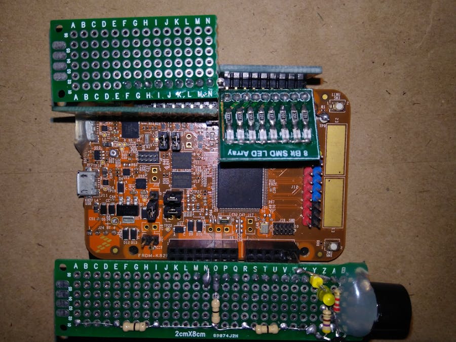
Method 2 : Kinetis Design StudioHardwareSince, this is just like a project template, all you need is the K82 Freedom board, some protoboard, LEDs and buzzer. Here is how my hardware looks like:
We will need to install the Kinetis Design Studio for writing code and Arduino IDE for using its built in serial monitor.
There is a void setup() and void loop() part in the middle of the code where you can write code in Arduino style:
Top part of main.c has header files and bottom part has Arduino function body. These areas should be untouched or the functions may malfunction!
Installation Instruction(Coming soon, after I prepare the screenshots)
First:
- Download and Install KDS (Kinetis Design Studio)
- Download and Install K82 Freedom Board Driver (if necessary)
- Download and Install K82 Freedom Board OpenSDA Bootloader (if necessary)
- Download SDK for Example Driver/Apps (optional)
Here is a Getting Started Video
- Download Project Generator (optional)
- Download the attached Code, save and unzip on your Computer.
Note:
To install the Bootloader, unplug the board, press & hold reset, plug the board into computer's USB. Now release reset button, drag and drop the bootloader bin file into the appeared USB Disk. Now, unplug and plug the K82 FRDM Board to boot SEGGER LINK Bootloader.
Now download the zip file from the Code section below, save on desktop and unzip it.
Step 1: Importing Existing Project
Open Kinetis Design Studio on your computer. Go to File>Import.
Select Projects for Projects>Next, then browse the downloaded unzipped files, find ArduinoFn_K82frdm.wsd and Open. Click Finish to complete Import.
Step 2: Opening and Editing Code
On the left column click on '+' of ArduinoFn_K82frdm_MK82FN256VLL15, now double click on the main.c file to open the code editor.
Scroll down to find the void setup() starts here comment, below this you will write setup functions in arduino style.
Scroll down a little to find the void loop() zone inside a while(1) loop, here is where you write code in Arduino style.
Scroll down further below, where you will find the arduino functions body written using kinetis design studio APIs, its better you don't modify them.
Step 3: Compiling, Flashing and Debugging
Look for the "Hammer", "Thunder" and "Bug" icons in KDS IDE (top second row) representing "Build/Compile Code", "Flash/Upload Code" and "Debug Code".
Write your code first, click the Hammer button to compile, Flash button to upload. But don't just Flash away, use Debug first.
On the top right corner there is a C/C++ button which is useful to come back to editor ( your code ) if you get lost in some other windows in the IDE.
Step 4: Configuring SEGGER J Link Debugger
If you have the right bootloader on your K82 Freedom board, you will have no trouble following the steps, if not download and install it on your board (see instructions before step 1 - above)
Click on the little down arrow next to the BUG icon, click debug configuration. Open the '+' left to GDB SEGGER J-Link Debugging and select
ArduinoFn_K82frdm_MK82FN256VLL15 debug J-Link and click debug. Click OK in the popup window. A terms of use (License B*** S***) window will appear, just accept anyway with checking "do not show this message again today". Your recompiling is running and code will flash to the hardware after few seconds.
If this error message shows up, click OK. Then click the C/C++ Tab ( top right corner ) to go back to code editor (main.c), click the Hammer button to compile again.
Once your code is flashed on the K82 Freedom board successfully this following debug window will appear. Click the Resume MCU button to startup your program on your Freedom board. There are many things on the debug window, unfortunately that is not with in the scope of this tutorial - so I am not going to explain these. Just check this image to see what is happening where during debugging.
Step 5: Serial Monitor on Arduino IDE
Open Arduino IDE on your computer, go to Tools > Port > COMxx, select the com port associated with Segger J-Link, in my case its COM20. On the top Right corner click on the Serial Monitor icon.
A window will appear, select baud rate 115200 if otherwise. You will see Streaming of Data from K82 Freedom board, does not it feel like Arduino by now?
For my code ADC value is popping on the screen.
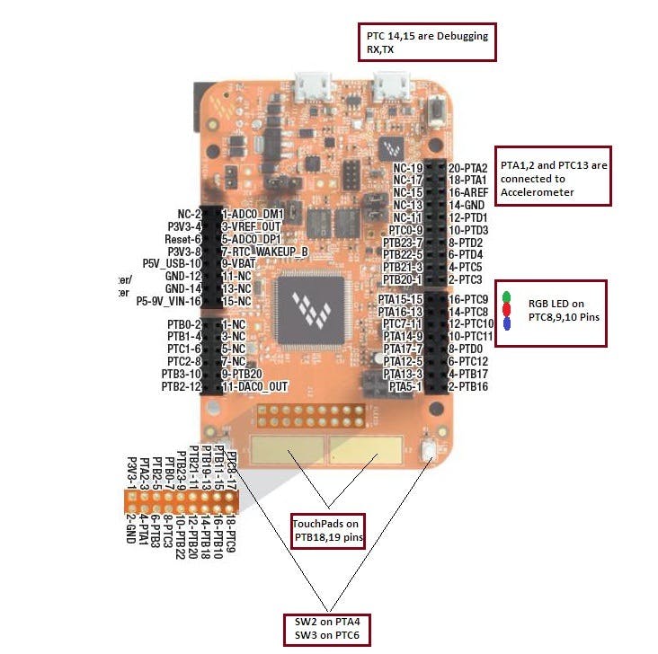
Some function are pin bound to specific pins, some pins are tied to the on board sensors, switches and LEDs. Carefully check this picture, so you get an idea which pins are not safe to use.
- Port C pin 14 & 15 are allocated for Serial, should not be used as GPIO
- Port A pin 4, Port C pin 6 are hardware connected to push switches SW2, SW3 thus should be used as GPIO Input
- Port C pin 8, 9 & 10 are allocated for PWM, should not be used as GPIO
- Port A pin 1 & 2 and Port C pin 13 are connected to on board sensor, should not be used as GPIO
- DAC0_Out is fixed for DAC output
- Port B pin 0, 1, 2 & 3 and Port C pin 1 & 2 are allocated for ADC
- All other available pins on the board may be used as GPIO
Since, I wanted to make sure I can use the additional pins out there on the board not the Arduino R3 layout covering pins, so some functions are slightly different than Arduino!
- pinMode()
In Arduino IDE we write pinMode(13, OUTPUT) but here it will different. Suppose I want to set Port B pin 20 as Output, what parameter should be passed?
By checking the bottom side of Freedom board, we find the physical location of the Port B Pin which is not on Arduino R3 layout but still can be used as GPIO!
The function will be pinMode('B',20,OUTPUT); here 'B' (Capital B with in ' ' is passed to indicate port ! This is how it's different from original Arduino function.
- digitalRead()
Example: To read PTA4 or Port A pin 4 we call digitalRead('A',4);
- digitalWrite()
Example: to write PTA5 or Port A pin 5 with High we call digitalWrite('A',5,HIGH);
- analogRead()
Since, analog pins are fixed and same as Arduino R3 location, function arguments are the same.
Example: analogRead the first ADC (PTB0 on this board) call analogRead(A0); in Arduino style or analogRead(B0); both will work the same and return a value with in 0-4095 range for 0-3.3 volts!
- analogWrite()
analogWrite is available on PTC 8, 9, 10 with duty cycle 0-100 (not 0-255 like Arduino) and 24000 Hz frequency (not 490 Hz like Arduino).
Example: analogWrite(8,25); turn on PWM on PTC8 pin/ port C pin 8 with 25% duty cycle.
- analogWriteDAC()
The DAC is 12 bit voltage DAC, so a value with in 0 to 4095 can be passed and and Analog Voltage will appear on DAC_OUT pin accordingly.
Example: analogWriteDAC(2048); will output around 1.67 volts on DAC pin
- delay()
Exactly same as Arduino, will halt the CPU!
Example: delay (500); will do 500 milliseconds or 0.5 seconds of delay
- Serial_println()
Same as Serial.pringln() in Arduino.
Example: Serial_println("Hello !"); will send the string "Hello !" over serial to the Serial Monitor of Arduino. Baud rate is fixed at 115200.
Here are some basic ideas what can be done after installing this code:
- High current load control through relay
- Analog sensor reading, monitoring and automation
- LED, Buzzer, Switch, 7-segment, Dot Matrix display driving
- DAC for waveform generation
- PWM Motor control for robotics
- UART communication
- Programming in Kinetis Design Studio not Arduino IDE
- Fixed Serial baud rate 115200 bps
- Possibility of Bug or Stall MCU
- Same pin may not support different functions during runtime
- 3 PWMs, 6 ADCs, 1 DAC are pin bound
- No SPI/I2C functions (until now)
- GPIO single pin current limit 25 mA, voltage 3.3 volt
- Total device GPIO limit 100 mA
- DAC current limit 1 mA (solution: use a voltage follower for drive)


_3u05Tpwasz.png?auto=compress%2Cformat&w=40&h=40&fit=fillmax&bg=fff&dpr=2)
Comments