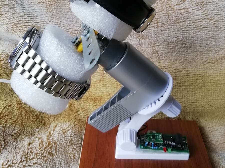
/*  ATtiny85 module controls using driver DRV8871, a DC motor (9V) to wind up to 4 automatic watches.
 *   The motor accelerates, rotates at Pwmax speed in one sense, deccelerates and stops.
 *   Then changes the sense an repeats the process.
 *   The cycles are repeated maxrun times. Then the whole process resumes after a psec (sec.) pause.
 *   Author: M.V. https://www.hackster.io/M-V-P
 *  Sketch for ATtiny85. Based on the Digispark (Use Digispark Default 16.5 MHz), no port select.
 *  Compile, Upload and then connect ATtiny85 module to USB cable.
 *  Programming ATtiny85 chip placed on Mini Usb MCU Development Board:
 *  https://www.banggood.com/ATTINY85-Mini-Usb-MCU-Development-Board-For-Arduino-p-971122.html?rmmds=myorder&cur_warehouse=CN
 *  - Adapter 6 pins to 8 pins (home made!)
 *  - USBASP 2.0 USB to SPI adapter:
 *  https://www.optimusdigital.ro/ro/programatoare/143-programator-avr-usbasp.html?search_query=programator&results=71
 * Select board: Digispark (default 16.5 MHz) or ATtiny/processor Attiny85/clock 8 MHz (internal)
 * Select programmer: USBasp
 *     Sketck/Upload Using Programmer (CTRL+SHIFT+U)
 *     it works, but a warning appears:
 *    avrdude: warning: cannot set sck period. please check for usbasp firmware update.
 * BETTER option: -Tools/Burn bootloader for ATtiny/processor Attiny85/clock 8 MHz (internal)
 *         - change the board: Digispark (default 16.5 MHz)
 *         - Sketck/Upload Using Programmer (CTRL+SHIFT+U)
 *  a) Using the ATtiny85 module: At POWER ON, the motor start running at full speed, until
 *  ATtiny85 module takes control. This means the first run has a different period than the next ones.
 *  All next cycles start when ATtiny85 wakes up after ~12H with progressive speed-up!
 *  b) Using ATtiny85 alone, the boot period is absent and MCU takes control from POWER-UP, slowly!
 * {ATtiny85 alone pins: 1=PB5, 2=PB3,ADC3, 3=PB4,ADC2, 4=GND, 5=PB0,MOSI,SDA, 6=PB1,MISO, 7=PB2,SCK,SCL, 8=VCC}
 *
 * ATtiny85 module (9V VIN)    DRV8871 Brushed DC Motor Driver (6.5-35V)
 * PB3                       = INT1
 * PB4                       = INT2
 *  ATtiny PB4 = Power for the driver (pin: 20mA = sufficient)
 *
 *  This work is licensed under the Creative Commons Attribution-       *
 * ShareAlike 3.0 Unported License. To view a copy of this license,     *
 * visit http://creativecommons.org/licenses/by-sa/3.0/ or send a       *
 * letter to Creative Commons, 171 Second Street, Suite 300,            *
 * San Francisco, California, 94105, USA.                               *
 * v6: adjusted watches rewind time
 * Sketch uses 3046 bytes (50%) of program storage space. Maximum is 6012 bytes.
 * Global variables use 86 bytes of dynamic memory.
 */


#include <TinyWireM.h>                  // I2C Master lib for ATTinys which use USI
// https://github.com/digistump/DigistumpArduino/tree/master/digistump-avr/libraries/DigisparkTinySoftPwm :
#include <TinySoftPwm.h>
// Utility sleep macros
// https://gist.github.com/JChristensen/5616922 :
#include <avr/sleep.h>
#include <avr/wdt.h>                    //Needed to enable/disable watch dog timer
#define adc_disable() (ADCSRA &= ~(1<<ADEN)) // disable ADC (before power-off)
#define adc_enable()  (ADCSRA |=  (1<<ADEN)) // re-enable ADC

#define LED_BUILTIN PB1         //
#define DRV1 PB3                //
#define DRV2 PB4                //
/*  DRV1    DRV2    = motor driver command pins
 *    0      0      => Coast (sleep after 1ms)
 *    0      1      => Reverse max speed  (PWM on DRV2)
 *    1      0      => Forward max speed  (PWM on DRV1)
 *    1      1      => Brake, with low decay
 */

unsigned int psec=43640;           // Period of the process = pause(~sec): 12h period (uint32_t<65535 !)
uint32_t StartStep=0, StartRot=0;  // Time counters
uint32_t runit, maxrun=8;          // rotate maxrun times  (10 => ~30 min)
int Pwm, Pwmin=60, Pwmax=255;      // Max speed from 255 possible
int  Dir, Sense;                   // Rotation direction: increasing/decreasing speed, and Sense: anti/clockwise
bool hold=false;

void setup()
{
  pinMode(DRV1,OUTPUT);     // Direction pin
  pinMode(DRV2,OUTPUT);     // Speed pin
 psec-=100*maxrun;        // Substract duration of rewind process (~100s: can be adjusted!)
 Dir=-1;                  //
 Sense=1;
 Pwm=Pwmin;
 runit=0;

  /***********************************************************/
  /* Call TinySoftPwm_process() with a period of 60 us       */
  /* The PWM frequency = 128 x 60 # 7.7 ms -> F # 130Hz      */
  /* 128 is the first argument passed to TinySoftPwm_begin() */
  /***********************************************************/
  TinySoftPwm_begin(128, 0); /* 128 x TinySoftPwm_process() calls before overlap (Frequency tuning), 0 = PWM init for all declared pins */
  set_sleep_mode(SLEEP_MODE_PWR_DOWN);  // sleep mode is set here
  sleep_enable();                       // enables the sleep bit in the mcucr register, so sleep is possible
}


//================================================================================================
void loop(){
  static uint32_t StartUs=micros();
  static uint32_t StartMs=millis();
  /***********************************************************/
  /* Call TinySoftPwm_process() with a period of 60 us       */
  /* The PWM frequency = 128 x 60 # 7.7 ms -> F # 130Hz      */
  /* 128 is the first argument passed to TinySoftPwm_begin() */
  /***********************************************************/
  if((micros() - StartUs) >= 60)
  { StartUs=micros();
   /* This function shall be called periodically, like here, based on micros() */
    TinySoftPwm_process();
  }

  /*************************************************************/
  /* Send commands to the motor with a period of 100 ms and    */
  /* ~60s hold on max speed => ~ 100.5s cycle period                */
  /*************************************************************/
  if((millis()-StartMs) >= 100)
  {
    digitalWrite(LED_BUILTIN, HIGH);// Automatically reset after ON!!
    StartMs=millis();               // reset timer
    Pwm-=Dir; /* increment or decrement PWM depending of sign of Dir */


    if(Pwm > Pwmax) {               /*If max speed is surpassed: */
      Pwm=Pwmax;                    /* Keep the max speed        */
      Dir=-1;                       /* Hold motor as accelerating*/
      if (hold==false){             /* First time Pwm>Pwmax :    */
        StartRot=millis();          /*  mark the moment,         */
        hold=true;                  /*  set max speed indicator. */
      }
    }

    if (millis()-StartRot > 60000 && hold==true){ /*Keep rotating at max speed for 60 s */
      Dir=1;                        /* After 60s: start reducing speed                  */
      hold=false;                   /* reset the max. indicator                         */
    }

    if (Sense==1){
       TinySoftPwm_analogWrite(DRV1, Pwm); /* Update driver speed control */
    }
    else{
       TinySoftPwm_analogWrite(DRV2, Pwm); /* Update driver speed control */
    }

    if(Pwm<=Pwmin){        /* if PWM reaches the minimum: */
      Pwm=Pwmin;
      Dir=-1;              /* start increasing speed      */
      Sense=-Sense;        /* and change rotation sense   */
      runit++;             /* Increase runs counter       */
      digitalWrite(LED_BUILTIN, LOW);
      waitsec(2);          /* A 2s break for the motor    */
    }
  }

  /* Keep runing maxrun times, then sleep: */
  if(runit>=maxrun){
    sleepsec(psec);          /* Have a pause/sleep of psec seconds */
    runit=0;                 /* Reset cycle counter                */
  }

}

//================================================================================================
//This runs each time the watch dog wakes us up from sleep
ISR(WDT_vect) {
  // The MCU wakes-up after every 8 sec. Then goes again to sleep if necessary!
}

//================================================================================================
void sleepsec(unsigned int seconds){
  // Tested for max. 65635 sec. = 18.15 hours
  volatile uint8_t i, j, imx, jmx;
  unsigned int cycles, rems;
  seconds -= seconds/100;     // Correction for Led ON duration (here adjust for 12H period!)
  cycles = seconds/9;         // Each sleep cycle lasts ~8.8s
  rems = seconds % 9;         // Seconds after cycles*9
  waitsec(rems);              // Pause MCU for rems seconds
  imx=cycles/256;             // Keep it in blocks of 255
  jmx=cycles % 256;           // and reminder of these blocks
  // AtTiny85 will sleep for "seconds", but each cycle is about 8.8s
  for (j=0; j<jmx; j++){
      setup_watchdog(9);      //Setup watchdog to go off (code 9 -> 8s sec + code time)
      sleep_mode();           //Go to sleep! Wake up n sec later and work
      digitalWrite(LED_BUILTIN, HIGH); // Every 8s, wake-up and Led ON
      delay(80);
      digitalWrite(LED_BUILTIN, LOW);
  }
  for (i=0; i<imx; i++){
    for (j=0; j<255; j++){
      setup_watchdog(9);      //Setup watchdog to go off (code 9 -> 8s sec + code time)
      sleep_mode();           //Go to sleep! Wake up n sec later and work
      digitalWrite(LED_BUILTIN, HIGH);
      delay(80);
      digitalWrite(LED_BUILTIN, LOW);
    }
  }

}

//================================================================================================
void waitsec(int seconds){
  unsigned long startsec=millis()/1000;
  while (millis()/1000-startsec < seconds){
    digitalWrite(LED_BUILTIN, HIGH);
    delay(100);
    digitalWrite(LED_BUILTIN, LOW);
    // Do nothing, just wait to pass "seconds".
  }
}

//================================================================================================
void setup_watchdog(int timerPrescaler) {
    //Sets the watchdog timer to wake up, but no reset, after:
    //0=16ms, 1=32ms, 2=64ms, 3=128ms, 4=250ms, 5=500ms
    //6=1sec, 7=2sec, 8=4sec, 9=8sec
    //From: http://interface.khm.de/index.php/lab/experiments/sleep_watchdog_battery/
  if (timerPrescaler > 9 ) timerPrescaler = 9; //Limit incoming amount to legal settings
  byte bb = timerPrescaler & 7;
  if (timerPrescaler > 7) bb |= (1<<5); //Set the special 5th bit if necessary
  //This order of commands is important and cannot be combined
  MCUSR &= ~(1<<WDRF);            //Clear the watchdog reset
  WDTCR |= (1<<WDCE) | (1<<WDE);  //Set WD_change enable, set WD enable
  WDTCR = bb;                     //Set new watchdog timeout value
  WDTCR |= _BV(WDIE);             //Set the interrupt enable, this will keep unit from resetting after each int
}


Comments