The FT232R is a USB to serial UART interface device which is equipped to power and program other modules via a USB A connector. The IP01 is required for programming the range of CPU Core xChips over the USB-serial bridge provided by the FT232R.
×
1
XinaBox OC05
The OC05 xChip is a servo motor controller driver that uses the PCA9685 PWM controller as servo interface supported by a BU33SD5 regulator to drive and accurately control up to 8 servo motors on a single module and act as system power supply. The module has 8 standard 2.54 mm (0.1") servo headers, plus 1 standard 2.54 mm (0.1") battery/BEC input header.
×
1
XinaBox SH01
This xChip is based on the CAP1296 which is a multiple channel capacitive touch sensor controller. The CAP1296 includes Multiple Pattern Touch recognition that allows the user to select a specific set of buttons to be touched simultaneously. If this pattern is detected, a status bit is set and an interrupt is generated.
×
1
XinaBox CC01
This xChip is a core CPU module, based on the ATmega328P, which is a single-chip microcontroller. The ATmega328P is the same architecture as Arduino Pro Mini, allowing users to program in the Arduino IDE and other IDEs supporting the Arduino Pro/Pro Mini, such as PlatformIO and Mbed.
I built this project to illustrate how a servo can be controlled using a capactive touch input. The servo driver is the OC05 xChip based off the PCA9685 and the capactive touch input is the SH01 based off CAP1296. The operation of the project is such that the user can press a 'button' on the SH01 to manoeuvre a servo 90° and 180° in either direction.
Step 1: Download Necessary Files
You will need the following libraries and software:
Once you've installed the Arduino IDE, open it up and select the "Arduino Pro or Pro Mini" as the board to upload your program to. Also make sure the ATmega328P (5V, 16MHz) processor is selected. See image below.
Select the Arduino Pro or Pro Mini board and the Atmega328P (5V, 16MHz) processor.
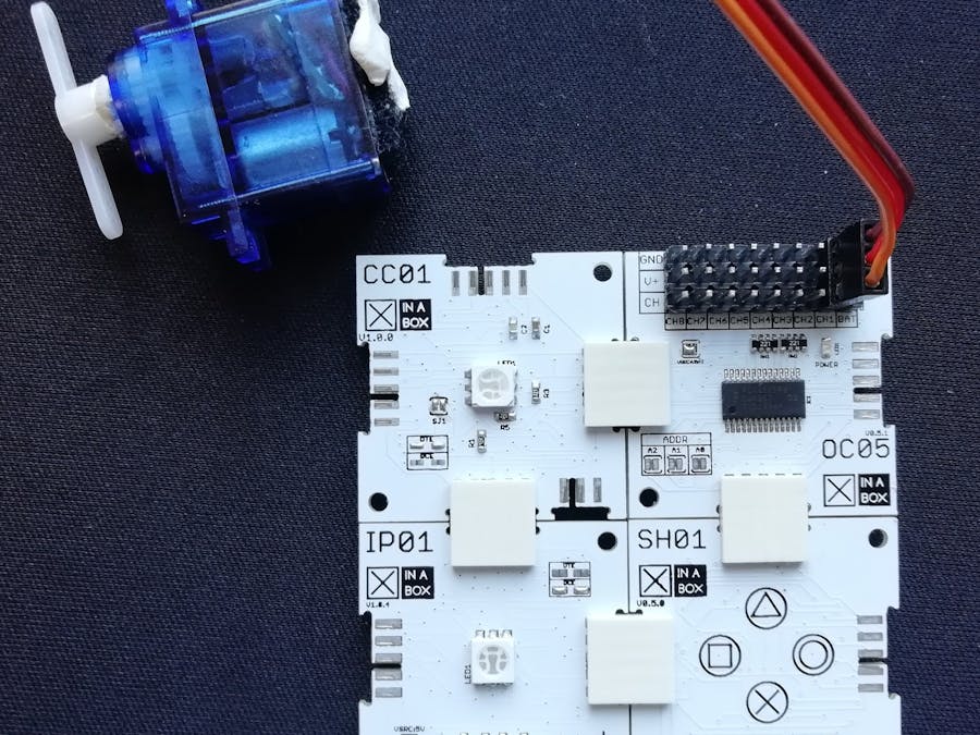
Step 2: Assemble
Assemble the project as per image below. A user simply needs to click together the xChips (general name for each module) using XC10 bus connectors. Connect the servo to channel 1 on the OC05 or which ever channel is desired as long as you account for the change in the code. The channel numbers are conveniently indicated on the OC05.
Final connections.
Step 3: Program
Insert IP01 into an available USB port on your computer. The Arduino IDE will detect the a new COM port; select it before trying to upload. Copy and paste the code under the code section into the Arduino IDE and upload the program to CC03 (Arduino Pro Mini clone).
The code below contains the functions responsible for positioning the servo. Comments are added explaining the functionality. View the entire code in the code section for a better understanding.
/*
  Rotate servo 180 degree to the left
*/
void servoLeft(void) {
 for (uint16_t pulselen = SERVO_MIN; pulselen < SERVO_MAX; pulselen++) {
   OC05.setPWM(SERVO_CHANNEL, 0, pulselen);
 }
}
/*
  Rotate servo 180 degree to the right
*/
void servoRight(void) {
 for (uint16_t pulselen = SERVO_MAX; pulselen > SERVO_MIN; pulselen--) {
   OC05.setPWM(SERVO_CHANNEL, 0, pulselen);
 }
}
/*
  Rotate servo 90 degree in either direction
*/
void servoCentre() {
 for (uint16_t pulselen = SERVO_CENTER;;) {
   if (pulselen < SERVO_MIN) {
     pulselen--;
   } else if (pulselen > SERVO_MAX) {
     pulselen++;
   }
   OC05.setPWM(SERVO_CHANNEL, 0, pulselen);
   if (pulselen == SERVO_CENTER) break; // exit loop when servo positions itself in the center
 }
}
Step 4: Operation
Once you've verified that code has been uploaded you may remove it from the computer. Grab a power bank or 5V USB power supply and insert the IP01 into it. By pressing the triangle touch button the servo will position itself upright (rotate 90°), the square button will rotate the servo to the left 90° relative to the center position and the circle button will rotate the servo 180° relative to left position. The video below demonstrates the operation.
Upload to Arduino Pro Mini board using the Arduino IDE.
// system includes
#include <xCore.h>#include <xOC05.h>#include <xSH01.h>// system defines
#define SERVO_CHANNEL 1 // OC05 channel number. Corresponds with OC05 xChip// values obtained experimentally
#define SERVO_MAX 650#define SERVO_MIN 100#define SERVO_CENTER 250// xchip instances
xOC05 OC05;xSH01 SH01;void setup(){ // put your setup code here, to run once:
// begin serial communication
Serial.begin(115200); // initiate i2c bus
Wire.begin(); // start OC05
OC05.begin(); // set servo frequency
OC05.setPWMFreq(50); // start SH01
SH01.begin();}void loop(){ // put your main code here, to run repeatedly:
// rotate servo to the left if square is touched
//if (SH01.touchDetected()){if(SH01.squareTouched()){ servoLeft();} // rotate servo to the right if circle is touched
elseif(SH01.circleTouched()){ servoRight(); // rotate servo to the center if triangle is touched
}elseif(SH01.triangleTouched()){ servoCenter();} delay(1000);}/*
Rotate servo 180 degree to the left
*/
void servoLeft(void){for(uint16_t pulselen= SERVO_MIN; pulselen < SERVO_MAX; pulselen++){ OC05.setPWM(SERVO_CHANNEL, 0, pulselen);}}/*
Rotate servo 180 degree to the right
*/
void servoRight(void){for(uint16_t pulselen= SERVO_MAX; pulselen > SERVO_MIN; pulselen--){ OC05.setPWM(SERVO_CHANNEL, 0, pulselen);}}/*
Rotate servo 90 degree in either direction
*/
void servoCenter(){for(uint16_t pulselen= SERVO_CENTER;;){if(pulselen < SERVO_MIN){ pulselen--;}elseif(pulselen > SERVO_MAX){ pulselen++;} OC05.setPWM(SERVO_CHANNEL, 0, pulselen);if(pulselen== SERVO_CENTER) break; // exit loop when servo positions itself in the center
}}


Comments