What is it ?
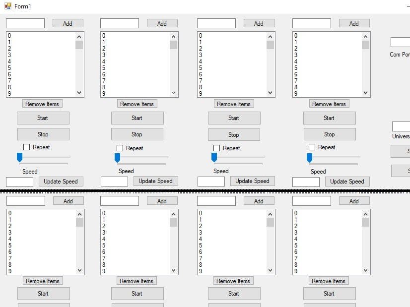
This project consists of an interface window where we can control up to 8 dimmable lamps and create any effect with them without having to reprogram the Arduino. This can be useful, for example, to create the lighting for a mini-disco. It is possible to have one light bulb blinking while another one is fading out and another perhaps fading on. Anyway, there are countless possibilities.
How it works ?
We enter the desired values for brightness level and our little app sends the numbers over the COM port (USB port the Arduino is connected to). For example, 114 could mean the lamp is off and 0 could mean the lamp is on. Therefore, the value 57 would be 50% of the brightness, etc. These are the same values we have to insert into our ListBox in our window. We then configure how we want to use these values. For example, to blink a light bulb, we enter 114 and then 0, activate the "repeat" checkbox, and then we can change the speed if we want. For example, to make the light bulb glow more and more, we put the values 0, 1, 2, 3, 4, 5, 6, .... up to 114 and then we say if we want to repeat and we can also change the speed . When opening the window, the values for fade in and fade out will appear by default. Whenever the application is started, it is necessary to enter the COM port (ex: COM1) that the Arduino is connected to and click on the "Open Port" button. Currently, there are many bugs, but it will work on all channels. The code is bad and needs to be optimized, but it will work. I'm not an experienced programmer and this project was done with little programming knowledge. It can work with an 1, 2, 3, 4, 5, 6, 7 or 8 channel AC dimmer module that works with the electrical network of home.
There are two ways to use the app. We can use it in sync mode or in normal mode. In normal mode, we use the individual buttons "Start" and "Stop" and in the CH field we leave it empty (in this case, with the CH field empty, it means that this socket will not be part of the set of sockets for synchronization and the channel to which it is socket will match will be equal to socket position number (counted from left to right horizontally row by row). The other way is to use in sync mode. In this mode, socket 1 must be used. It is through his values of brightness and options ( like repeat ) that it will be controlled the other sockets we want to use. Suppose we are going to use sockets 1,2 and 3 for the respective channels 1,2 and 3. We enter the values in the CH fields (these values must be equal to the socket position numbers), we edit the brightness values using the "Add" and "Remove Items" buttons and press "Start All". The brightness items for each socket will be synced. The "mother" control for all sockets used is on the first socket ( Note: all sockets used must have the same amount of brightness value items). For the sockets we don't want to use for sync, we simply leave the CH field empty (socket number matches channel number). The "Stop All" button stops the sockets used for synchronization.
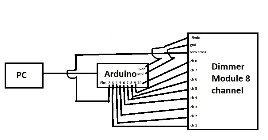
Application -> Arduino -> Module -> Lamps
This is a work in progress...


_ztBMuBhMHo.jpg?auto=compress%2Cformat&w=48&h=48&fit=fill&bg=ffffff)


Comments