// Auduino, the Lo-Fi granular synthesiser
//
// by Peter Knight, Tinker.it http://tinker.it
//
// Help: http://code.google.com/p/tinkerit/wiki/Auduino
// More help: http://groups.google.com/group/auduino
//
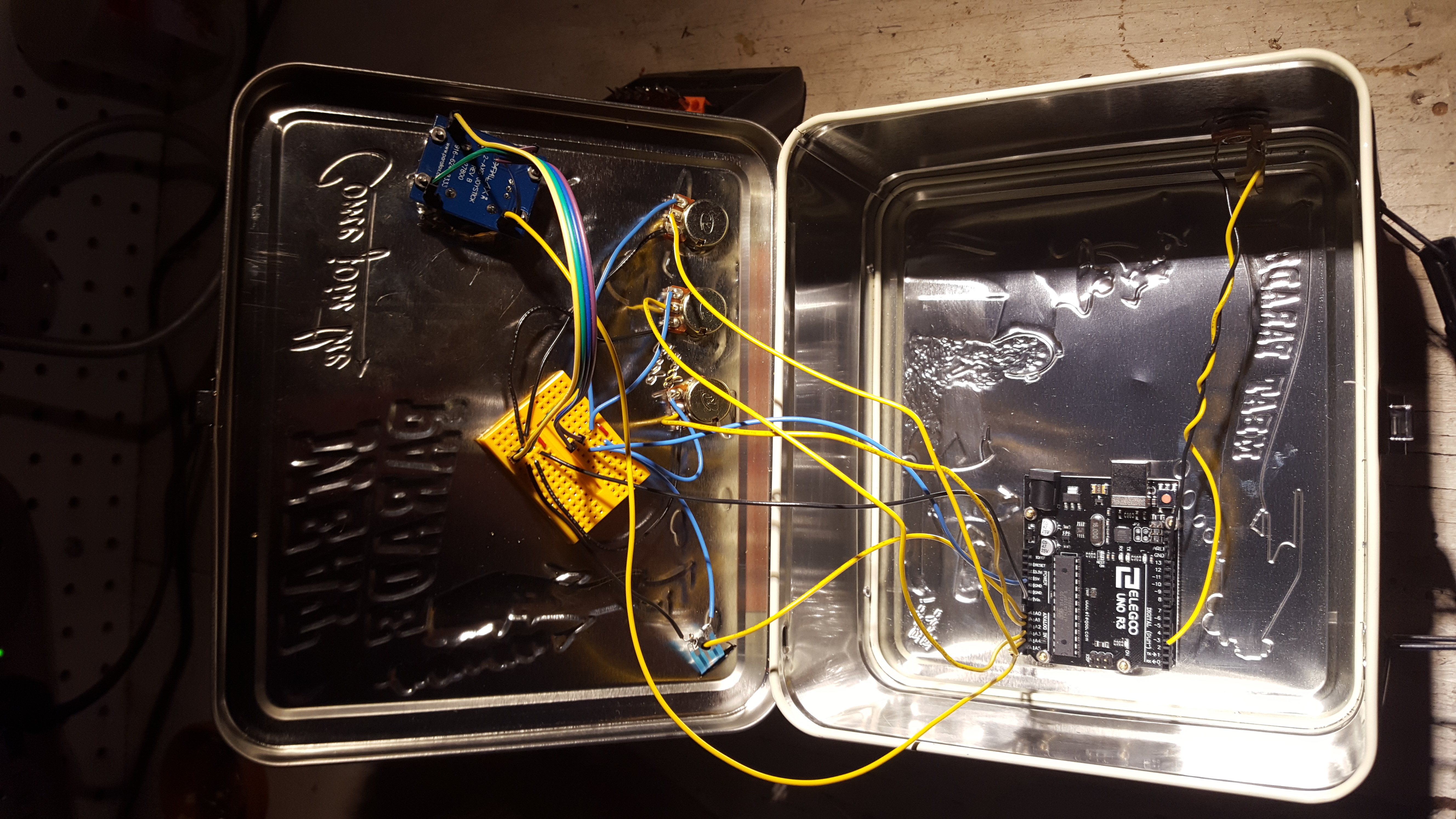
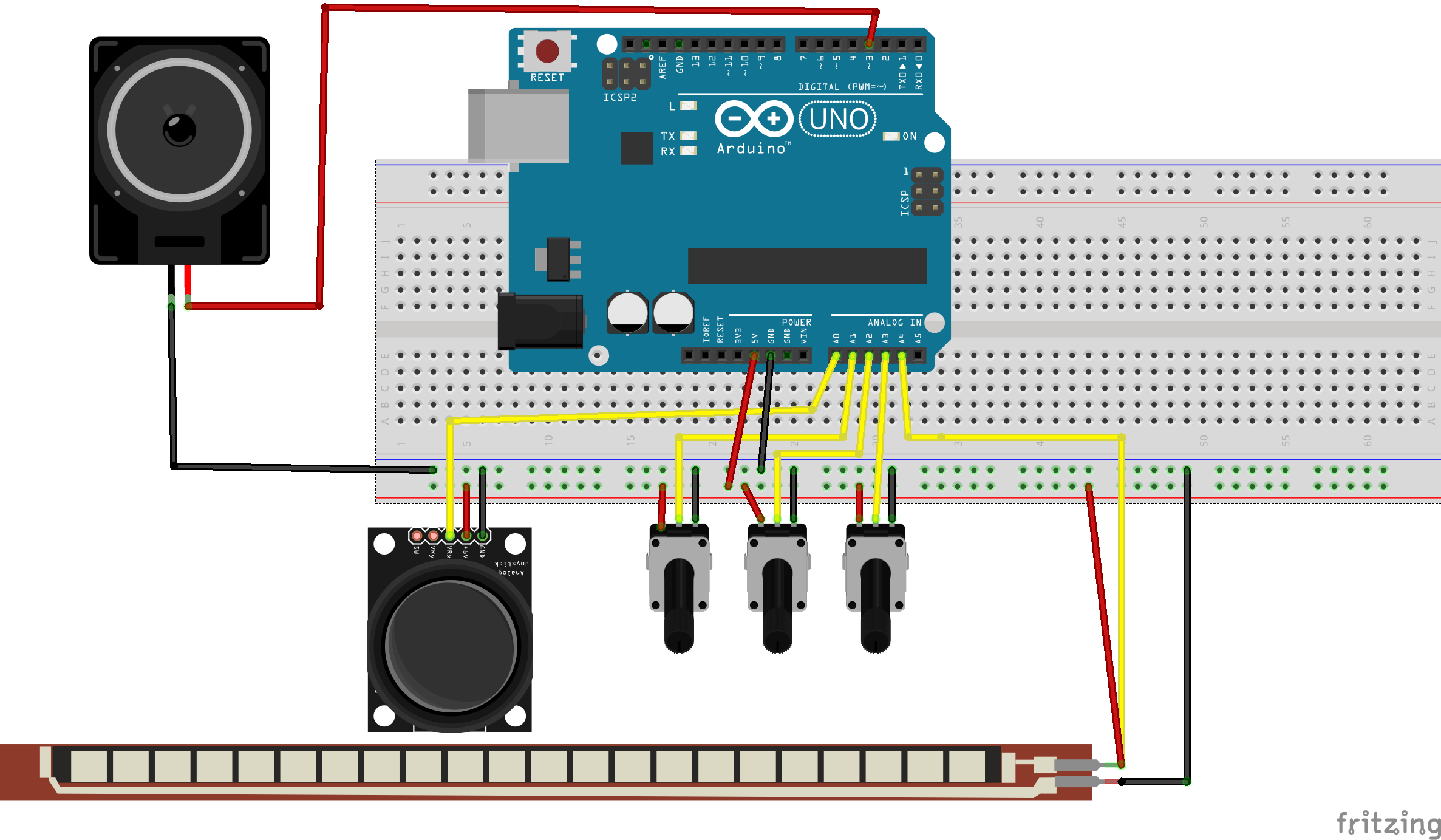
// Analog in 0: Grain 1 pitch
// Analog in 1: Grain 2 decay
// Analog in 2: Grain 1 decay
// Analog in 3: Grain 2 pitch
// Analog in 4: Grain repetition frequency
//
// Digital 3: Audio out (Digital 11 on ATmega8)
//
// Changelog:
// 19 Nov 2008: Added support for ATmega8 boards
// 21 Mar 2009: Added support for ATmega328 boards
// 7 Apr 2009: Fixed interrupt vector for ATmega328 boards
// 8 Apr 2009: Added support for ATmega1280 boards (Arduino Mega)
#include <avr/io.h>
#include <avr/interrupt.h>
uint16_t syncPhaseAcc;
uint16_t syncPhaseInc;
uint16_t grainPhaseAcc;
uint16_t grainPhaseInc;
uint16_t grainAmp;
uint8_t grainDecay;
uint16_t grain2PhaseAcc;
uint16_t grain2PhaseInc;
uint16_t grain2Amp;
uint8_t grain2Decay;
// Map Analogue channels
#define SYNC_CONTROL (4)
#define GRAIN_FREQ_CONTROL (0)
#define GRAIN_DECAY_CONTROL (2)
#define GRAIN2_FREQ_CONTROL (3)
#define GRAIN2_DECAY_CONTROL (1)
// Changing these will also requires rewriting audioOn()
#if defined(__AVR_ATmega8__)
//
// On old ATmega8 boards.
// Output is on pin 11
//
#define LED_PIN 13
#define LED_PORT PORTB
#define LED_BIT 5
#define PWM_PIN 11
#define PWM_VALUE OCR2
#define PWM_INTERRUPT TIMER2_OVF_vect
#elif defined(__AVR_ATmega1280__)
//
// On the Arduino Mega
// Output is on pin 3
//
#define LED_PIN 13
#define LED_PORT PORTB
#define LED_BIT 7
#define PWM_PIN 3
#define PWM_VALUE OCR3C
#define PWM_INTERRUPT TIMER3_OVF_vect
#else
//
// For modern ATmega168 and ATmega328 boards
// Output is on pin 3
//
#define PWM_PIN 3
#define PWM_VALUE OCR2B
#define LED_PIN 13
#define LED_PORT PORTB
#define LED_BIT 5
#define PWM_INTERRUPT TIMER2_OVF_vect
#endif
// Smooth logarithmic mapping
//
uint16_t antilogTable[] = {
64830,64132,63441,62757,62081,61413,60751,60097,59449,58809,58176,57549,56929,56316,55709,55109,
54515,53928,53347,52773,52204,51642,51085,50535,49991,49452,48920,48393,47871,47356,46846,46341,
45842,45348,44859,44376,43898,43425,42958,42495,42037,41584,41136,40693,40255,39821,39392,38968,
38548,38133,37722,37316,36914,36516,36123,35734,35349,34968,34591,34219,33850,33486,33125,32768
};
uint16_t mapPhaseInc(uint16_t input) {
return (antilogTable[input & 0x3f]) >> (input >> 6);
}
// Stepped chromatic mapping
//
uint16_t midiTable[] = {
17,18,19,20,22,23,24,26,27,29,31,32,34,36,38,41,43,46,48,51,54,58,61,65,69,73,
77,82,86,92,97,103,109,115,122,129,137,145,154,163,173,183,194,206,218,231,
244,259,274,291,308,326,346,366,388,411,435,461,489,518,549,581,616,652,691,
732,776,822,871,923,978,1036,1097,1163,1232,1305,1383,1465,1552,1644,1742,
1845,1955,2071,2195,2325,2463,2610,2765,2930,3104,3288,3484,3691,3910,4143,
4389,4650,4927,5220,5530,5859,6207,6577,6968,7382,7821,8286,8779,9301,9854,
10440,11060,11718,12415,13153,13935,14764,15642,16572,17557,18601,19708,20879,
22121,23436,24830,26306
};
uint16_t mapMidi(uint16_t input) {
return (midiTable[(1023-input) >> 3]);
}
// Stepped Pentatonic mapping
//
uint16_t pentatonicTable[54] = {
0,19,22,26,29,32,38,43,51,58,65,77,86,103,115,129,154,173,206,231,259,308,346,
411,461,518,616,691,822,923,1036,1232,1383,1644,1845,2071,2463,2765,3288,
3691,4143,4927,5530,6577,7382,8286,9854,11060,13153,14764,16572,19708,22121,26306
};
uint16_t mapPentatonic(uint16_t input) {
uint8_t value = (1023-input) / (1024/53);
return (pentatonicTable[value]);
}
void audioOn() {
#if defined(__AVR_ATmega8__)
// ATmega8 has different registers
TCCR2 = _BV(WGM20) | _BV(COM21) | _BV(CS20);
TIMSK = _BV(TOIE2);
#elif defined(__AVR_ATmega1280__)
TCCR3A = _BV(COM3C1) | _BV(WGM30);
TCCR3B = _BV(CS30);
TIMSK3 = _BV(TOIE3);
#else
// Set up PWM to 31.25kHz, phase accurate
TCCR2A = _BV(COM2B1) | _BV(WGM20);
TCCR2B = _BV(CS20);
TIMSK2 = _BV(TOIE2);
#endif
}
void setup() {
pinMode(PWM_PIN,OUTPUT);
audioOn();
pinMode(LED_PIN,OUTPUT);
}
void loop() {
// The loop is pretty simple - it just updates the parameters for the oscillators.
//
// Avoid using any functions that make extensive use of interrupts, or turn interrupts off.
// They will cause clicks and poops in the audio.
// Smooth frequency mapping
//syncPhaseInc = mapPhaseInc(analogRead(SYNC_CONTROL)) / 4;
// Stepped mapping to MIDI notes: C, Db, D, Eb, E, F...
//syncPhaseInc = mapMidi(analogRead(SYNC_CONTROL));
// Stepped pentatonic mapping: D, E, G, A, B
syncPhaseInc = mapPentatonic(analogRead(SYNC_CONTROL));
grainPhaseInc = mapPhaseInc(analogRead(GRAIN_FREQ_CONTROL)) / 2;
grainDecay = analogRead(GRAIN_DECAY_CONTROL) / 8;
grain2PhaseInc = mapPhaseInc(analogRead(GRAIN2_FREQ_CONTROL)) / 2;
grain2Decay = analogRead(GRAIN2_DECAY_CONTROL) / 4;
}
SIGNAL(PWM_INTERRUPT)
{
uint8_t value;
uint16_t output;
syncPhaseAcc += syncPhaseInc;
if (syncPhaseAcc < syncPhaseInc) {
// Time to start the next grain
grainPhaseAcc = 0;
grainAmp = 0x7fff;
grain2PhaseAcc = 0;
grain2Amp = 0x7fff;
LED_PORT ^= 1 << LED_BIT; // Faster than using digitalWrite
}
// Increment the phase of the grain oscillators
grainPhaseAcc += grainPhaseInc;
grain2PhaseAcc += grain2PhaseInc;
// Convert phase into a triangle wave
value = (grainPhaseAcc >> 7) & 0xff;
if (grainPhaseAcc & 0x8000) value = ~value;
// Multiply by current grain amplitude to get sample
output = value * (grainAmp >> 8);
// Repeat for second grain
value = (grain2PhaseAcc >> 7) & 0xff;
if (grain2PhaseAcc & 0x8000) value = ~value;
output += value * (grain2Amp >> 8);
// Make the grain amplitudes decay by a factor every sample (exponential decay)
grainAmp -= (grainAmp >> 8) * grainDecay;
grain2Amp -= (grain2Amp >> 8) * grain2Decay;
// Scale output to the available range, clipping if necessary
output >>= 9;
if (output > 255) output = 255;
// Output to PWM (this is faster than using analogWrite)
PWM_VALUE = output;
}


_ztBMuBhMHo.jpg?auto=compress%2Cformat&w=48&h=48&fit=fill&bg=ffffff)


Comments