


Hardware components | ||||||
 |
| × | 1 | |||
| × | 1 | ||||
| × | 1 | ||||
 |
| × | 1 | |||
 |
| × | 1 | |||
 |
| × | 1 | |||
 |
| × | 1 | |||
 |
| × | 1 | |||
| × | 1 | ||||
| × | 1 | ||||
| × | 1 | ||||
| × | 1 | ||||
| × | 1 | ||||
Software apps and online services | ||||||
 |
| |||||
 |
| |||||
| ||||||
 |
| |||||
| ||||||
| ||||||
| ||||||
Hand tools and fabrication machines | ||||||
 |
| |||||
 |
| |||||
 |
| |||||
Inspired by the tragic 2020 styrene gas leak in Visakhapatnam (Vizag), this project addresses a critical gap in disaster response: the delay between an accident and safe human intervention. During the Vizag incident, toxic gas spread rapidly into residential areas while people were asleep, forcing first responders to enter unknown and life-threatening conditions without real-time information on gas concentration or environmental safety.
The motivation behind BOLT (Quadruped Robotic Dog) stems from a simple yet life-saving question:
“Why should humans enter dangerous zones before machines?”
BOLT is designed to act as the first set of eyes, ears, and sensors on the ground, gathering critical environmental data before any human responder steps into danger. By combining quadrupedal mobility, modular sensing, and real-time wireless data transmission, this project establishes a foundation for a deployable robotic scout capable of operating in toxic, unstable, or inaccessible environments.
Problem StatementDespite advancements in emergency response, large-scale industrial accidents such as gas leaks, chemical spills, mine collapses, and structural failures continue to place responders at extreme risk. The primary challenge in these scenarios is the “Information Gap”—the time between the occurrence of a disaster and the moment it becomes safe for humans to assess the situation.
Existing robotic solutions often suffer from one or more of the following limitations:
- High cost, making them inaccessible to local municipalities
- Limited mobility over debris and uneven terrain
- Single-purpose design with little adaptability
As a result, responders frequently operate with incomplete or no situational awareness. BOLT addresses this gap by offering a low-cost, high-mobility, modular quadruped platform capable of traversing complex terrain while carrying swappable sensor payloads. This ensures that human entry occurs only after risks are measured and understood.
BOLT is equipped with environmental sensors to detect hazardous gases, structural instability, and unsafe conditions before human entry
Solution OverviewBOLT is designed as a four-legged robotic platform optimized for disaster-site navigation. Unlike wheeled robots that struggle with rubble, stairs, or uneven surfaces, a quadruped provides:
- A stable four-point stance
- Better adaptability to terrain variation
- Controlled body posture during sensing operations
At the core of BOLT’s design is modularity. The robot uses a centralized compute unit paired with standardized electrical and software interfaces, allowing rapid swapping of sensor modules based on mission requirements. Whether the scenario involves gas detection, structural assessment, landmine reconnaissance, or subterranean air-quality analysis, BOLT can be reconfigured without redesigning the platform.
This approach transforms BOLT from a single-use robot into a multi-scenario robotic framework.
Hardware ArchitectureMaterials Used- Main Controller: Raspberry Pi 5
- Supporting Controller : Teensy 4.1
- Motor Controller: MKS ODrive Mini
- Actuators: Eagle Power 90KV BLDC Motors
- Gear Reduction: 9:1 Metal Gearboxes
- Power Source: 3S Li-Po Battery (11.1V)
- Structure: 3D-printed chassis and leg segments
- Sensors: Gas sensors, IMU (MPU6050), camera modules
Each leg joint is powered by a 90KV BLDC motor coupled with a 9:1 gearbox, trading rotational speed for torque. The motor’s initial high RPM is reduced to approximately 140 RPM at the output, significantly increasing torque to around 16 Nm per joint.
This torque level allows BOLT to:
- Maintain stable posture on uneven ground
- Support body weight during crouching or climbing
- Execute slow, controlled movements essential for sensing accuracy
The MKS ODrive Mini is used for closed-loop BLDC motor control. It provides:
- Field-Oriented Control (FOC)
- Encoder-based position and velocity feedback
- Precise torque and position control required for legged locomotion
This setup eliminates the limitations of basic H-bridge drivers and enables smooth, precise joint motion—critical for quadruped stability.
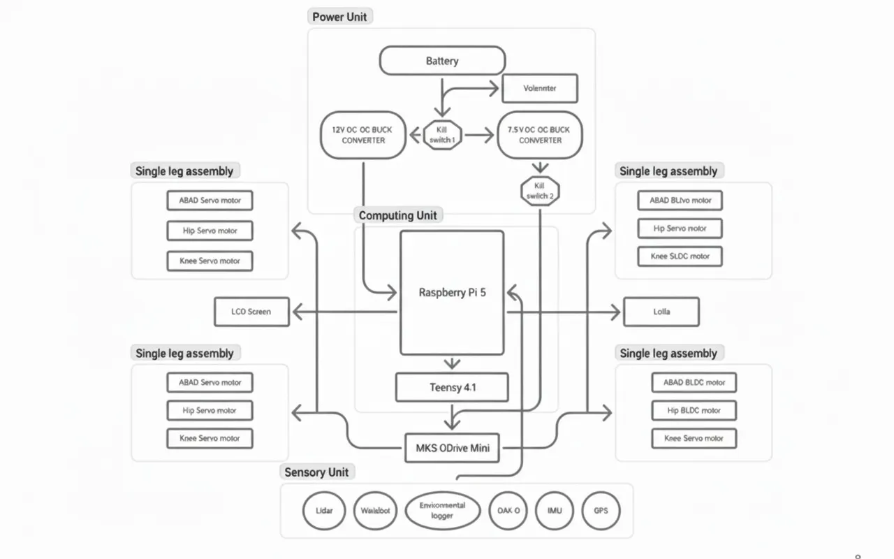
Electronics architectureBOLT follows a layered control architecture commonly used in advanced robotic systems, where computation, real-time control, and actuation are handled by dedicated hardware layers. This design ensures stability, scalability, and reliable operation in hazardous environments.
1. High-Level Control Layer — Raspberry Pi (The Brain)The Raspberry Pi serves as the high-level processing unit of BOLT.
Responsibilities:
- Runs ROS2 Humble
- Executes gait planning and inverse kinematics (IK)
- Handles sensor fusion (camera, environmental sensors)
- Manages wireless communication with the operator
- Publishes joint position or velocity commands
The Raspberry Pi does not control motors directly. Instead, it computes what the robot should do and sends structured motion commands to the real-time controller.
2. Real-Time Control Layer — Teensy Microcontroller (The Controller)The Teensy acts as the deterministic real-time controller of the system.
Why Teensy is required:
- Raspberry Pi runs Linux → non-deterministic timing
- Quadruped locomotion requires:
- High-frequency motor updates
- Precise synchronization across 12 joints
- Immediate reaction to feedback
Responsibilities:
- Receives joint commands from the Raspberry Pi via USB serial
- Parses joint angle / velocity setpoints
- Enforces motion limits and safety constraints
- Generates real-time control signals for motor drivers
- Reads encoder and IMU feedback
This separation ensures stable locomotion even under high computational load on the Pi.
3. Motor Control Layer — MKS ODrive MiniThe MKS ODrive Mini is used as the high-performance motor driver for BOLT’s actuators.
Key functions:
- Drives Eagle Power 90KV BLDC motors
- Performs field-oriented control (FOC)
- Handles current, velocity, and position loops
- Provides encoder feedback to the Teensy
Communication:
- Teensy communicates with the ODrive Mini using CAN
- Each motor is assigned a dedicated control channel
- Control frequency remains consistent regardless of Pi load
The ODrive Mini handles the low-level power electronics, while the Teensy remains responsible for coordination and timing.
4. Actuation Layer — Eagle Power 90KV Motors + GearboxesEach leg of BOLT uses three Eagle Power 90KV BLDC motors, paired with 9:1 metal gearboxes.
Mechanical outcome:
- Motor speed reduced from ~1260 RPM to ~140 RPM
- Output torque increased to approximately 16 Nm
Enables:
- Load-bearing stance
- Controlled stepping over debris
- Stable crouching in confined space
This configuration provides the torque density required for a quadruped robot without excessive power consumption.
5. Power Distribution Architecture3S LiPo (11.1V) powers:
- MKS ODrive Mini
- BLDC motor
Buck converters step down voltage to:
- 5V for Raspberry Pi
- 5V / 3.3V for Teensy and sensors
All subsystems share a common ground to ensure reliable communication and prevent signal instability
6. Overall Control Flow SummaryROS2 Nodes (IK, Planning, Teleop)
↓
Raspberry Pi
↓ (USB Serial)
Teensy
↓ (CAN)
MKS ODrive Mini
↓
Eagle Power 90KV Motors (12x)This architecture allows BOLT to function as a safe, scalable, and modular robotic platform, capable of operating in environments where real-time performance and reliability are non-negotiable.
Nodeguard module placement(Optional)As part of the modular design, BOLT integrates NodeGuard, an independent sensing and monitoring system developed separately. Instead of redesigning the sensing stack from scratch, the complete NodeGuard unit is mounted onto the quadruped platform and used as a plug-and-play module for hazard detection.
This approach allows NodeGuard to remain a standalone system while benefiting from BOLT’s mobility. Details of NodeGuard’s internal design are not covered in this document and can be accessed through the project link below.
https://www.hackster.io/514275/nodeguard-wioterminal-mqtt-air-quality-monitor-2529c4
Software Architecture: ROS2 EcosystemBOLT is built entirely around ROS2, the industry-standard middleware for modular and scalable robotic systems. ROS2 enables reliable communication between high-level decision making, real-time motor control, and environmental sensing.
The software architecture follows a distributed publisher–subscriber model, ensuring that locomotion, sensing, and visualization remain independent yet synchronized.
Core ROS2 NodesTeleoperation Node
- Accepts operator commands as velocity inputs
- Commands are generated via keyboard or remote workstation
Gait & Inverse Kinematics Node
- Converts velocity commands into coordinated leg trajectories
- Computes hip and knee joint angles using inverse kinematics
- Ensures stable gait patterns over uneven terrain
Motor Interface Node
- Packages joint angle and velocity commands
- Transmits them to the Teensy 4.1 via serial / micro-ROS
- Acts as the bridge between ROS2 and low-level motor control
Commands are forwarded to the Teensy, which publishes position and torque setpoints over CAN to the ODrive Mini controllers.
Low-Level Control (Teensy + ODrive Mini)
- Teensy receives joint commands from ROS2
- Converts commands into ODrive Mini setpoints
- ODrive Mini performs closed-loop BLDC motor control using encoder feedback
Sensor Nodes
- Gas sensor node publishes real-time gas concentration data
- Temperature sensor node publishes ambient thermal readings
- All sensor data is streamed as ROS2 topics for monitoring and logging
- Operator sends motion commands via ROS2 teleop
- Gait planner computes foot trajectories
- IK node calculates joint angles
- Commands are sent to Teensy
- Teensy controls ODrive Mini motor drivers
- Sensors publish environmental data in parallel
This architecture ensures real-time motor control, modular sensor integration, and safe remote operation, making BOLT a reliable first-response robotic platform for hazardous environments.
Mission-Level Communication & Tracking (Meshtastic LoRa Network)1️⃣ Wio Tracker L1 Lite (Onboard Robotic Dog Node)The robotic dog carries a Wio Tracker L1 Lite, a compact LoRa-based Meshtastic node integrated inside the chassis. This module operates independently of the main ROS2 control stack, ensuring continuous tracking even during communication or system failures.
Functions in BOLT:
- Publishes real-time GPS location of the robot to the Meshtastic mesH
- Broadcasts robot status (active, idle, fault, low battery)
- Acts as a mobile relay node to extend mesh coverage
Technical Advantages:
- Operates in the 862–930 MHz band for long-range communication
- Ultra-low power consumption suitable for long missions
- nRF52840 MCU enables basic sensor interfacing if needed
- Compact form factor for internal mounting
Rescue personnel carry SenseCAP Card Tracker T1000-E devices, which act as personal Meshtastic nodes within the same LoRa mesh as the robotic dog.
Functions in the Mission:
- Provides continuous GPS tracking of responders
- Acts as relay nodes to extend mesh range in collapsed or underground areas
- Enables location-aware coordination between humans and robots
Key Characteristics:
- Credit-card-sized, rugged form factor
- LR1110 LoRa radio with high sensitivity
- nRF52840 MCU for low-power operation
- Designed specifically for Meshtastic field deployment
The Hazard Response Mission Pack serves as the central aggregation and decision-making unit for the operation.
Responsibilities:
- Collects LoRa data from the robotic dog and rescue personnel
- Aggregates GPS, gas, temperature, and status data
- Runs higher-level analytics and alert logic
- Bridges LoRa mesh data to dashboards and visualization tools
System Capabilities:
- Open-source AIoT framework for rapid integration
- Supports additional sensors beyond tracking
- Can host visualization servers or alert systems
- Operates as a LoRa-to-IP gateway for command interfaces
End-to-End Mission Communication Flow
- The robotic dog transmits its GPS position and health data via the Wio Tracker L1 Lite.
- Rescue personnel nodes relay their own positions and forward mesh traffic.
- All data converges at the Hazard Response Mission Pack.
- Operators visualize robot paths, gas zones, and human locations in real time.
- Decisions are made without exposing humans to unknown hazards.
BOLT is equipped with a focused environmental sensing system designed specifically for hazardous gas detection and thermal monitoring. These sensors provide first responders with critical situational awareness before human entry into unsafe zones.
Integrated SensorsGas Sensors
- Detect hazardous industrial gases such as CO, methane, and volatile organic compounds
- Used to identify high-risk “hot zones” during leaks or confined-space incidents
Temperature Sensor
- Monitors ambient temperature
- Useful for detecting abnormal heat signatures caused by chemical reactions, fires, or equipment failures
All sensors are electrically isolated from the motor power system to prevent noise and interference.
Modular Sensor SystemThe sensing system on BOLT is implemented using a modular ROS2-based architecture. Each sensor operates independently of the locomotion stack and publishes data as ROS2 topics.
The modular sensor interface also supports subsurface sensing devices such as imaging radar modules for landmine and unexploded ordnance detection.
Sensor Architecture- Gas sensors are interfaced through the Teensy and sampled at a fixed rate
- Temperature sensor readings are continuously streamed to the Raspberry Pi
- Sensor data is forwarded to ROS2 without affecting gait control or motor timing
- Sensors can be upgraded or replaced without changing locomotion code
- Data remains available even if the robot is stationary
- Critical readings are transmitted in real time to the operator
If unsafe gas levels or abnormal temperatures are detected, the information is immediately visible to the operator, allowing informed decisions without physical exposure.
Inverse Kinematics and Gait EngineQuadruped locomotion requires precise control of foot placement, not direct motor rotation. BOLT uses an Inverse Kinematics (IK) engine to compute joint angles based on desired foot positions in Cartesian space.
How It Works- The operator issues movement commands using ROS2 teleop
- A gait planner generates swing and stance phases for each leg
- The IK solver computes hip and knee joint angles using trigonometric relationships (Law of Cosines)
- Joint targets are transmitted from the Raspberry Pi to the Teensy
- The Teensy forwards real-time position commands to the MKS ODrive Mini, which executes closed-loop motor control
This layered approach ensures smooth, stable locomotion even on uneven terrain such as rubble, debris, or collapsed structures.
Inverse Kinematics (IK) Derivation for Quadruped Leg ControlINVERSE KINEMATICS
OverviewFor stable and precise quadruped locomotion, BOLT does not directly command motor rotations. Instead, it computes joint angles that place each foot at a desired 3D position relative to the robot body. This process is handled using Inverse Kinematics (IK).
Inverse Kinematics determines the required joint angles given a target foot position, enabling smooth walking, crouching, and obstacle traversal.
1. Physical Model and Coordinate DefinitionsEach leg of BOLT is modeled as a three-link, three-degree-of-freedom (3-DOF) mechanism.
Coordinate System- The coordinate origin is located at the Abduction–Adduction (Abad) joint
- The desired foot position is defined as:
where:
- x: forward/backward direction
- y: lateral (sideways) direction
- z: vertical direction
To simplify the trigonometric solution, several intermediate quantities are defined.
Total ReachThe squared distance from the Abad joint to the foot:
The projection of the foot position onto the horizontal (x–y) plane:
The effective distance from the Hip joint to the foot, accounting for the lateral offset:
This forms a triangle between the thigh (b), calf (c), and the baseline distance(d).
3. Solving for Joint AnglesStep 1: Knee Angle (θ3)The knee angle is calculated using the Law of Cosines on the triangle formed by the thigh, calf, and baseline distance:
Interpretation:
This determines how much the lower leg must bend to reach the target foot position.
The hip angle is computed by resolving two intermediate angles:
- α: angle due to vertical foot displacement
- β: angle caused by the thigh orientation
The final hip angle is:
Interpretation:
This angle positions the thigh so the leg reaches the desired height and forward position.
The Abad angle controls lateral movement and compensates for the hip offset:
Interpretation:
This rotates the entire leg assembly outward or inward to align with the target foot position.
- Desired foot trajectories are generated by the gait planner
- IK computes joint angles for each leg independently
- Joint angles are sent to the ODrive Mini via CAN
- Closed-loop torque control ensures smooth and stable motion
This IK-based control approach allows BOLT to adapt its posture dynamically, enabling stable locomotion across uneven terrain and debris.
4. Final Joint Angle SummaryTo place the foot at position (x,y,z) BOLT computes:
Build InstructionsStep 0: Mechanical Design and 3D PrintingDesign Parts in CAD
- Create leg segments, motor mounts, and gearbox housings.
- Include reinforced ribs for load-bearing parts.
- Add internal channels for wire routing.
- Standardize mounting points for future upgrades.
Select Materials
- Use PLA+ for initial prototypes (easy and fast to print).
- Print high-stress parts (hip mounts, knee joints) in PETG for strength.
- Increase infill density for components under continuous load.
Set Printing Parameters
- Layer height: 0.2 mm
- Infill: 30–50% (gyroid pattern for strength)
- Wall thickness: 1.6–2 mm
- Print orientation: layer lines perpendicular to major stress directions
Post-Processing
- Sand mating surfaces to remove layer artifacts.
- Test-fit bearin seats and motor mounts, adjust if necessary.
- Install heat-set threaded inserts for durable screw connections.
Quality Check
- Ensure proper alignment of all moving parts
- Verify structural integrity before moving to electronics integration..
Outcome
Mechanically robust platform ready for motors, electronics, and control systems.
Step 1: Mechanical Assembly of the Quadruped FrameBefore working on electronics, the mechanical structure must be assembled to ensure correct motor alignment and load distribution.
1.1 Assemble the ChassisUse 3D-printed for:
- Central body
- Hip moun
- Upper and lower leg segment
- Secure all joints using metal fasteners, not plastic screws
- Ensure symmetry between left and right legs to avoid gait imbalance
- Attach the Eagle Power 90KV BLDC motors to the 9:1 metal gearboxes
- Gearbox output shafts are aligned with joint axes
- No binding during manual rotation
Each leg uses 3 motors:
- Hip roll
- Hip pitch
- Knee pitch(Total: 12 motors)
- Motor speed (approx.): 1260 RPM
- After 9:1 gearbox: ~140 RPM
- Output torque: ~16 Nm
This configuration allows:
- Stable stance
- Load-bearing crouch
- Controlled stepping over rubble
A stable power system is critical for high-torque robotics.
2.1 Battery Configuration- Use a 3S LiPo battery (11.1V)
Battery powers:
- MKS ODrive Mini
- BLDC motors
- Battery powers:MKS ODrive MiniBLDC motors
Use buck converters to step down:
- 11.1V → 5V (Raspberry Pi)
- 11.1V → 5V / 3.3V (Teensy & sensors)
⚠️ Important:All components must share a common ground to prevent communication errors.
Step 3: Electronics Architecture SetupBecause the Raspberry Pi has limited GPIO pins and runs a non-real-time OS, it does NOT control motors directly.
Control Hierarchy:Raspberry Pi (High-Level Control)
↓
Teensy 4.1 (Real-Time Control)
↓
MKS ODrive Mini (Motor Driver)
↓
Eagle Power 90KV MotorsThe Teensy controls all 12 motors and handles timing-critical tasks.
4.1 Required Components- Teensy 4.1
- USB Micro-B cable
- Computer with Arduino IDE
- Download Teensyduino from PJRC
- Install it into Arduino IDE
Select:
- Board: Teensy 4.1
- USB Type: Serial
Upload the following code to verify communication:
void setup() {
  Serial.begin(115200);
}

void loop() {
  if (Serial.available()) {
    char c = Serial.read();
    Serial.print("Received: ");
    Serial.println(c);
  }
}ls /dev/ttyACM*
screen /dev/ttyACM0 115200Type characters and confirm Teensy echoes them back.
Step 6: Configuring the MKS ODrive Mini (Motor Control & Calibration)The MKS ODrive Mini is responsible for precise control of the Eagle Power 90KV BLDC motors using Field-Oriented Control (FOC). Before BOLT can walk, each motor must be properly configured, calibrated, and tested.
This step ensures that:
- Motors spin in the correct direction
- Encoders provide accurate position feedback
- Current limits are safely configured
- Closed-loop control is stable
- MKS ODrive Mini
- Eagle Power 90KV BLDC motors
- Encoder (incremental or magnetic)
- USB cable
- Computer (Linux recommended)
- Python 3 installed
The odrivetool is the official command-line interface used to configure and debug ODrive-based motor controllers.
Install dependencies:
sudo apt update
sudo apt install python3-pip
pip3 install --user odrive
Verify installation:
odrivetool --version- Connect the ODrive Mini to your computer using USB
- Power the board using the 3S LiPo (11.1V)
- Launch the tool:
odrivetoolYou should see:
Connected to ODrive
In [1]:
This opens an interactive Python shell where you can directly access motor parameters.
6.4 Motor and Encoder ConfigurationEach motor axis must be configured individually.
6.4.1 Set Motor Parametersodrv0.axis0.motor.config.pole_pairs = 7
odrv0.axis0.motor.config.motor_type = MOTOR_TYPE_HIGH_CURRENT
odrv0.axis0.motor.config.current_lim = 25Explanation:
pole_pairs: depends on the BLDC motor (verify datasheet)current_lim: limits torque to prevent damage- High-current mode enables stable startup under load
odrv0.axis0.encoder.config.mode = ENCODER_MODE_INCREMENTAL
odrv0.axis0.encoder.config.cpr = 8192
Then save configuration:
odrv0.save_configuration()The ODrive will reboot automatically.
6.5 Motor Calibration SequenceCalibration aligns the motor phases and encoder reference.
odrv0.axis0.requested_state = AXIS_STATE_FULL_CALIBRATION_SEQUENCEDuring calibration:
- Motor will rotate slowly
- Encoder offset is measured
- Electrical phase alignment is established
⚠️ Safety Warning:Secure the motor firmly. Do not touch moving parts during calibration.
Check calibration result:
odrv0.axis0.motor.is_calibrated
odrv0.axis0.encoder.is_ready
Both should return True.
Switch to closed-loop control:
odrv0.axis0.requested_state = AXIS_STATE_CLOSED_LOOP_CONTROLTest position control:
odrv0.axis0.controller.config.control_mode = CONTROL_MODE_POSITION_CONTROL
odrv0.axis0.controller.input_pos = 1.0
The motor should rotate smoothly to the target position.
Because BOLT uses a 9:1 gearbox, it is important to verify correct direction:
odrv0.axis0.controller.input_pos = -1.0If motion is reversed:
odrv0.axis0.motor.config.direction = -1
odrv0.save_configuration()To prevent leg damage:
odrv0.axis0.controller.config.vel_limit = 10
odrv0.axis0.controller.config.input_mode = INPUT_MODE_PASSTHROUGH
This ensures:
- Smooth stepping
- No sudden jerks
- Controlled crouching motion
Repeat Steps 6.4 – 6.8 for:
axis0andaxis1- All ODrive Mini boards used (12 motors total)
Label each motor:
FL_HIP,FL_KNEE, etc.This avoids confusion during ROS integration.
Once calibration is complete:
- Disconnect USB
- Connect Teensy via CAN
- Teensy sends position/velocity commands
- ODrive runs in closed-loop autonomously
At runtime:
- Raspberry Pi computes motion
- Teensy enforces real-time timing
- ODrive executes motor-level control
After calibrating all motors using the MKS ODrive Mini, the next step is to program the Teensy 4.1, which acts as the real-time motion controller for BOLT. The Teensy bridges high-level commands from the Raspberry Pi and low-level motor execution handled by the ODrive.
This step ensures:
- Deterministic motor updates for all 12 joints
- Safe parsing of joint commands
- Reliable communication with the ODrive Mini
Although the Raspberry Pi is powerful, it runs Linux and cannot guarantee millisecond-level timing. Quadruped locomotion requires precise, synchronized motor updates, which is why Teensy is introduced.
Teensy responsibilities:
- Receive joint targets from Raspberry Pi
- Maintain fixed control loop timing
- Communicate with MKS ODrive Mini ( CAN)
- Enforce joint limits and safety rules
- React instantly to sensor events (tilt, fall)
- Teensy 4.1
- USB Micro-B cable
- Arduino IDE + Teensyduino
- Logic-level CAN transceivers (if required)
- MKS ODrive Mini (already calibrated)
- Open Arduino IDE
Select:
- Board: Teensy 4.1
- USB Type: Serial
- Set baud rate to 115200
Communication between the Teensy and MKS ODrive Mini is handled via CAN bus for deterministic, low-latency motor control
7.5 Sending Basic Commands to ODriveTest communication by placing the motor in closed-loop mode:
void sendODriveCommand(const char* cmd) {
  ODRIVE_SERIAL.println(cmd);
}

void setup() {
  Serial.begin(115200);
  ODRIVE_SERIAL.begin(115200);

  sendODriveCommand("w axis0.requested_state 8"); // CLOSED_LOOP_CONTROL
}

void loop() {
}
If the motor enters closed-loop mode without errors, communication is working correctly.
7.6 Multi-Motor Mapping (12-Joint Configuration)Each motor is assigned a logical joint ID.
Joint ID
Description
0
Front-Left Hip-1
Front-Left Knee -2
This abstraction allows the Raspberry Pi to send joint arrays instead of individual motor commands.
7.7 Parsing Joint Commands from Raspberry PiTeensy receives structured packets over USB serial.
Example packet:
J,0,1.25Meaning:
- Joint 0
- Target position = 1.25 radians
void loop() {
  if (Serial.available()) {
    String cmd = Serial.readStringUntil('\n');
    int joint;
    float pos;
    sscanf(cmd.c_str(), "J,%d,%f", &joint, &pos);
    moveJoint(joint, pos);
  }
}Joint setpoints are transmitted over CAN using ODrive’s CAN protocol, where each axis is addressed via its CAN node ID.
void moveJoint(int joint, float position) {
  char buffer[64];
sprintf(buffer, "w axis%d.controller.input_pos %f", axis, position);
}
This enables:
- Smooth joint movement
- Coordinated gait execution
- Centralized safety checks
To prevent mechanical damage:
float clamp(float value, float minVal, float maxVal) {
  return max(minVal, min(value, maxVal));
}
Applied before sending commands:
position = clamp(position, -2.0, 2.0);A fixed-rate loop ensures synchronization across all joints.
elapsedMicros loopTimer;

void loop() {
  if (loopTimer > 2000) { // 500 Hz
    loopTimer = 0;
    updateMotors();
  }
}
This ensures stable locomotion regardless of Raspberry Pi load.
Step 7 OutcomeAt the end of this step:
- Teensy reliably controls all 12 motors
- ODrive Mini executes smooth closed-loop motion
- System is ready for ROS2 integration
BOLT now has a deterministic motor control backbone, essential for safe operation in disaster environments.
Step 8: Setting Up the Raspberry Pi (High-Level Control)The Raspberry Pi acts as the high-level controller, responsible for gait planning, inverse kinematics, and system coordination.
FOR CORRECT SETUP REFERING THE OFFICIAL DOC IS THE BEST :
https://ubuntu.com/download/raspberry-pi
Actions:
- Flash Ubuntu 22.04 LTS onto the Raspberry Pi
- Enable SSH and Wi-Fi
- Update system packages
sudo apt update && sudo apt upgradeFOR CORRECT SETUP REFERING THE OFFICIAL DOC IS THE BEST :
https://docs.ros.org/en/humble/Installation/Ubuntu-Install-Debs.html
ROS2 is used as the main robotics middleware.
sudo apt install ros-humble-desktop
source /opt/ros/humble/setup.bash
ROS2 enables:
- Modular software design
- Sensor and motor abstraction
- Real-time visualization and debugging
mkdir -p ~/bolt_ws/src
cd ~/bolt_ws
colcon build
source install/setup.bash
Essential packages:
sudo apt install ros-humble-teleop-twist-keyboard \
                 ros-humble-rviz2 \
ros-humble-xacroMicro-ROS allows the Teensy to appear as a native ROS2 node.
On Raspberry Pi:
git clone -b humble https://github.com/micro-ROS/micro_ros_setup.git
ros2 run micro_ros_setup create_agent_ws.sh
ros2 run micro_ros_setup build_agent.sh
Run agent:
ros2 run micro_ros_agent micro_ros_agent serial --dev /dev/ttyACM0This enables direct publishing of joint commands and sensor data.
Step 12: Inverse Kinematics & Gait GenerationThe Raspberry Pi calculates joint angles using inverse kinematics.
Key concepts:
- Each foot follows a semi-elliptical trajectory
- Swing and stance phases are time-synchronized
- Joint angles are computed using trigonometry
Output is streamed to Teensy as joint position targets.
Step 13: Sensor Integration (Modular Payloads)Sensors are split based on latency requirements:
- High-latency sensors (camera, mapping) → Raspberry Pi
- Low-latency sensors (IMU, tilt detection) → Teensy
All sensor data is published as ROS2 topics, allowing easy expansion.
Step 14: Visualization & MonitoringRViz2 is used as the main command and monitoring interface.
ros2 run rviz2 rviz2Operators can view:
- Robot posture (URDF)
- IMU orientation
- Environmental sensor data
- Camera feed
All subsystems are launched using a single ROS2 launch file.
ros2 launch bolt_description robot_launch.pyInitial tests are performed at low speed to verify:
- Joint synchronization
- Stability
- Communication reliability
BOLT is designed around a sensor-agnostic, modular architecture. All sensors operate as independent ROS2 publishers, ensuring that sensing remains decoupled from locomotion and control logic.
Supported Sensors- Gas concentration sensors (industrial leaks, toxic exposure)
- IMU (tilt detection, fall monitoring)
- Camera modules (visual reconnaissance)
- Expandable interfaces for landmine detection or radiation sensors
Low-latency sensors are processed directly on the Teensy for immediate reaction, while high-level data is streamed to the Raspberry Pi and forwarded to the operator in real time.
Visualization and MonitoringBOLT uses RViz2 as its primary monitoring interface.
Using RViz2, operators can:
- View the 3D robot model (URDF)
- Monitor real-time sensor data
- Observe robot orientation, stability, and posture
This enables first responders to evaluate conditions and plan safe entry strategies without physical exposure to hazards.
Mission dashboard integrates Meshtastic GPS data from robot and personnel
Use Cases1. Industrial Gas Leak ResponseBOLT is deployed into contaminated zones to map gas concentration levels, allowing responders to remain at a safe distance of 50–100 meters while receiving live environmental data.
The robot’s position and gas data are simultaneously tracked alongside responder locations via a LoRa mesh network, ensuring coordinated and safe deployment.
2. Post-Earthquake Search and InspectionHigh-torque joints powered by 9:1 gearboxes (~16 Nm) allow BOLT to crouch and navigate beneath debris, providing visual and structural insights without risking secondary collapse.
3. Subterranean Safety ChecksEquipped with oxygen and methane sensors, BOLT can inspect mines, tunnels, or sewage systems to verify air safety before human entry.
4.Minefield Reconnaissance & Unexploded Ordnance DetectionEquipped with walabot to be capable of detecting mines
Things To Do: Autonomous Navigation & MappingAutonomous Perception and Mapping (Planned Upgrade)While BOLT currently operates in teleoperated mode, future versions are designed to support semi-autonomous and fully autonomous navigation. This will be achieved by integrating depth vision and LiDAR-based mapping systems, enabling BOLT to perceive, understand, and navigate complex environments without direct human control.
To support this upgrade, two key sensing systems will be introduced:
- OAK-D Pro stereo depth camerA
- 2D/3D LiDAR sensor
These sensors will allow BOLT to perform real-time mapping, obstacle detection, and localization in hazardous environments.
OAK-D PRO CAMERA INTEGRATION (PLANNED UPGRADE)Purpose- Depth perception
- Visual SLAM support
- Obstacle detection
- Terrain understanding
Mechanical Mounting
- Mount the OAK-D Pro at the front of the robot chassis with a forward-facing orientation.
- Ensure vibration isolation to maintain stereo depth accuracy.
Electrical Connection
- Connect the OAK-D Pro directly to the Raspberry Pi using a USB 3.0 interface.
- Provide adequate power supply as per OAK-D Pro specifications.
Software Installation
- Install the DepthAI SDK on the Raspberry Pi.
- Verify camera streams using DepthAI demo tools.
ROS2 Integration
- Install the
depthai-rospackage. - Launch ROS2 nodes to publish:
- RGB image topics
- Depth image topics
- Point cloud data
SLAM Compatibility
- Feed point cloud and image topics into a ROS2-compatible SLAM stack (e.g., RTAB-Map).
- Validate depth accuracy in indoor and low-light conditions.
- Accurate distance measurement
- Environment mapping
- Localization (2D/3D SLAM)
- Redundancy in low-visibility conditions
Sensor Mounting
- Mount the LiDAR at an elevated position to provide a 360° or wide-angle scan.
- Ensure the scan plane is not obstructed by robot legs or body parts.
Power and Communication
- Connect the LiDAR to the Raspberry Pi via USB, or Ethernet (based on LiDAR model)
- Provide stable power as per manufacturer requirements.
Driver Installation
- Install the appropriate ROS2 LiDAR driver package
- Verify raw scan data using ROS2 visualization tools.
ROS2 Topic Publishing
- Publish laser scan or point cloud data as standard ROS2 topics.
- Confirm correct frame IDs and coordinate alignment.
Mapping Integration
- Integrate LiDAR data with ROS2 SLAM frameworks such as Cartographer or SLAM Toolbox.
- Fuse LiDAR data with IMU for improved localization accuracy.
In hazardous environments such as minefields or conflict zones, threats may not be visible on the surface. To address this, BOLT is designed to support subsurface sensing modules, enabling detection of buried landmines or unexploded ordnance (UXO).
The Walabot imaging radar is planned as a modular add-on sensor that allows BOLT to scan beneath the ground surface before human entry, significantly reducing risk to personnel.
🔧 WALABOT SETUP — STEP-BY-STEP (DETAILED)Step 1: Mechanical Integration- Mount the Walabot module on the underside or front-lower section of the robot body.
- Maintain close proximity to the ground (as required by Walabot operating range).
- Use a vibration-isolated bracket to minimize motion artifacts during scans.
- Ensure the sensor does not interfere with leg motion or terrain clearance.
- Connect the Walabot to the Raspberry Pi via USB.
- Ensure sufficient power delivery according to Walabot specifications.
- No real-time motor control dependency — Walabot operates independently of locomotion timing.
- Install Walabot SDK and drivers on the Raspberry Pi.
- Verify device detection using Walabot diagnostic tools.
- Run sample scans to confirm subsurface imaging functionality.
- Wrap Walabot SDK outputs into a custom ROS2 node.
- Publish detected subsurface anomalies as ROS2 topics.
- Standardize output format for integration with autonomy stack.
Process Walabot data to identify:
- Density change
- Metallic/non-metallic anomalies
- Object depth estimation
- Trigger alerts when subsurface threats are detected.
- Overlay detection zones onto mapping data (LiDAR + SLAM).
- Display Walabot detection regions in RViz2.
- Provide color-coded risk indicators.
- Allow operator to halt movement if a threat is detected.
Once both sensors are active, BOLT will support:
- Visual-Inertial SLAM
- LiDAR-based Mapping
- Sensor Fusion (Camera + LiDAR + IMU)
- Autonomous Path Planning
- Obstacle Avoidance
These capabilities will allow BOLT to:
- Navigate gas-filled environments
- Traverse collapsed structures
- Operate in zero-visibility conditions
We are using Roboflow to create a machine learning model for the detection of landmines.
RoboflowRoboflow empowers developers to build their own computer vision applications, no matter their skillset or experience. It has over 2, 00, 000 datasets that can be used for classification, detection and segmentation tasks. A fast, easy-to-use, production-ready inference server for computer vision supporting deployment of many popular model architectures and fine-tuned models.
We have created an annotated dataset of landmines that has over 3900 images. These images are then classified into training sets, validation sets, and test sets.
A complete dataset goes through two main stages: pre-processing and augmentation. Pre-processing helps machines learn faster by making data consistent. For example, auto-orienting rotates tilted images upright. Augmentation, on the other hand, adds variations to the data to make the machine learning model more robust. One example of augmentation is a horizontal flip, which flips the image.
Another augmentation is shear, which makes images look slanted as if they were taken from a moving car. The speaker recommends using shear augmentation for data collected from street view where images are mostly straight-on.
Roboflow offers a variety of augmentation options, but the speaker sticks with the basic ones including auto-orient and horizontal flip. With these augmentations, the number of images in the dataset will be tripled from the original 860 to around 2, 000.At the preprocessing steps we have chosen to process images in our dataset,. We have chosen to resize the images, use static crop and auto-orientation.
Augmentation is a technique used to artificially increase the size of a dataset by creating modified versions of the existing data. This is important because it helps the machine learning model perform better on unseen data. It encourages the machine learning algorithm to see different images and still understand if they are slightly different. We have chose to crop and rotate the datasets.
After Augmentation our dataset was increased to 9400 Images. After training the datasets Roboflow will automatically show us the training graphs.
We have to verify whether our model is working properly or not. For that purpose we can deploy our model in Webcam itself.
Creating a Custom ML model using YoloV5
Here, we use a Google Colaboratory environment to perform training on the cloud.Step 1 : Click here to move on to already created workspace.
Step 2: Assembling the Dataset
Step 3: Train your model
Training a machine learning algorithm takes time but even if it takes a long time to train, you now have a rapidly deployable model. In the case of damage detection, it means a lot when you train this model and hit play in this line of code. What it's going to do is find the weights of what a destroyed home is, find the weights of what a non-destroyed home is and really evaluate based on all that information to be used in the future. So in the case we just want to do speed and get the notebook over with, then we might sacrifice determining whether someone's home is damaged and that means a lot and as urban planners and researchers, we really must consider all the implications to learn more about social biases and how machine learning really works at a deeper level.
After training, a PyTorch file is generated. We can deploy the PyTorch file in Nvidia Orin.
Custom TinyML model for Land Mine detectionIn this part, we'll kick off by labeling our dataset with the intuitive tools provided by Roboflow. From there, we'll advance to training our model within Google Colab's collaborative environment. Next up, we'll explore deploying our trained model using the SenseCraft Model Assistant, a process designed to smoothly bridge the gap between training and real-world applications. By the conclusion of this part, you'll have your very own custom model ready to detect butterfly mine, operational on oakd pro.
From dataset to model deployment, our journey consists of the following key stages:
1. Dataset Labeling — This section details the process of acquiring datasets suitable for training models. There are two primary methods: utilizing labeled datasets from the Roboflow community or curating your own dataset with scenario-specific images, necessitating manual labeling.
2. Model Training with Google Colab — Here, we focus on training a model capable of deployment on OAK D PRO, leveraging the dataset obtained in the previous step via the Google Colab platform.
3. Model Upload via SenseCraft Model Assistant — This segment explains how to employ the exported model file to upload our elephant detection model to OAK D PRO using the SenseCraft Model Assistant.Continue and you'll then get the Raw URL for this model. Keep it, we'll use the link in the model training step a bit later.
Step 1.Create a free Roboflow account
Roboflow provides everything you need to label, train, and deploy computer vision solutions. To get started, create a free Roboflow account.
Step 2. Creating a New Project and Uploading images
Once you've logged into Roboflow, Click on Create Project.
Name your project ("landmine detection"). Define your project as Object Detection. Set the Output Labels as Categorical
Now it's time to upload Landmine images.
Collect images of landmine. Ensure you have a variety of backgrounds and lighting conditions. On your project page, click "Add Images".
You can drag and drop your images or select them from your computer. Upload at least 100 images for a robust dataset.
click on Save and Continue
Step 3: Annotating Images
After uploading, you'll need to annotate the images by labeling elephant.
Roboflow offers three different ways of labelling images: Auto Label, Roboflow Labeling and Manual Labeling.
Auto Label: Use a large generalized model to automatically label images.
Auto Label: Use a large generalized model to automatically label images.
Auto Label: Use a large generalized model to automatically label images.
- Auto Label: Use a large generalized model to automatically label images.
Roboflow Labeling: Work with a professional team of human labelers. No minimum volumes. No upfront commitments. Bounding Box annotations start at $0.04 and Polygon annotations start at $0.08.
Roboflow Labeling: Work with a professional team of human labelers. No minimum volumes. No upfront commitments. Bounding Box annotations start at $0.04 and Polygon annotations start at $0.08.
Roboflow Labeling: Work with a professional team of human labelers. No minimum volumes. No upfront commitments. Bounding Box annotations start at $0.04 and Polygon annotations start at $0.08.
- Roboflow Labeling: Work with a professional team of human labelers. No minimum volumes. No upfront commitments. Bounding Box annotations start at $0.04 and Polygon annotations start at $0.08.
Manual Labeling: You and your team label your own images.
Manual Labeling: You and your team label your own images.
Manual Labeling: You and your team label your own images.
- Manual Labeling: You and your team label your own images.
The following describes the most commonly used method of manual labelling.
Click on "Manual Labeling" button. Roboflow will load the annotation interface.
Select the "Start Annotating" button. Draw bounding boxes around the landmine in each image.
Label each bounding box as elephant.
Use the ">" button to move through your dataset, repeating the annotation process for each image.
Step 4: Review and Edit Annotations
It's essential to ensure annotations are accurate.
Review each image to make sure the bounding boxes are correctly drawn and labeled. If you find any mistakes, select the annotation to adjust the bounding box or change the label.
Step 5: Generating and Exporting the Dataset
Once all images are annotated. In Annotate click the Add x images to Dataset button in the top right corner.
Then click the Add Images button at the bottom of the new pop-up window.
Click Generate in the left toolbar and click Continue in the third Preprocessing step.
In the Augmentation in step 4, select Mosaic, which increases generalisation.
In the final Create step, please calculate the number of images reasonably according to Roboflow's boost; in general, the more images you have, the longer it takes to train the model. However, the more pictures you have will not necessarily make the model more accurate, it mainly depends on whether the dataset is good enough or not.
Click on Create to create a version of your dataset. Roboflow will process the images and annotations, creating a versioned dataset. After the dataset is generated, click Export Dataset. Choose the COCO format that matches the requirements of the model you'll be training.
Click on Continue and you'll then get the Raw URL for this model. Keep it, we'll use the link in the model training step a bit late
Congratulations! You have successfully used Roboflow to upload, annotate, and export a dataset for elephant detection model. With your dataset ready, you can proceed to train a machine learning model using platforms like Google Colab.
Training Dataset Exported Model
Training Dataset Exported Model Step 1. Access the Colab Notebook
You can find different kinds of model Google Colab code files on the SenseCraft Model Assistant's Wiki. If you don't know which code you should choose, you can choose any one of them, depending on the class of your model (object detection or image classification).
If you are not already signed into your Google account, please sign in to access the full functionalities of Google Colab.
Click on "Connect" to allocate resources for your Colab session.
select the panel showing RAM and Disk
select "Change runtime type"
Select "T4 GPU"
Now run the "Setup SSCMA"
you will get a warning like this click on "Run anyways"
Wait untill the repositary is fully clonedand installed all the dependencies.
now its finished
Now run the "download the pretrain model weights file
Step 2. Add your Roboflow Dataset
Before officially running the code block step-by-step, we need to modify the code's content so that the code can use the dataset we prepared. We have to provide a URL to download the dataset directly into the Colab filesystem.
To customize this code for your own model link from Roboflow:
1)Replace Gesture_Detection_Swift-YOLO_192 with the desired directory name where you want to store your dataset.
2)Replace the Roboflow dataset URL (https://universe.roboflow.com/ds/xaMM3ZTeWy?key=5bznPZyI0t)
with the link to your exported dataset (It's the Raw URL we got in the last step in Labelled Datasets). Make sure to include the key parameter if required for access.
3)Adjust the output filename in the wget command if necessary
(-O your_directory/your_filename.zip).4)Make sure the output directory in the unzip command matches the directory you created and the filename matches the one you set in the wget command.
Step 3. Adjustment of model parameters
The next step is to adjust the input parameters of the model. Please jump to the Train a model with SSCMA section and you will see the following code snippet.
This command is used to start the training process of a machine learning model, specifically a YOLO (You Only Look Once) model, using the SSCMA (Seeed Studio SenseCraft Model Assistant) framework.
To customize this command for your own training, you would:
1)Replace configs/swift_yolo/swift_yolo_tiny_1xb16_300e_coco.py with the path to your own configuration file if you have a custom one.
2)Change work_dir to the directory where you want your training outputs to be saved.
3)Update num_classes to match the number of classes in your own dataset. It depends on the number of tags you have, for example rock, paper, scissors should be three tags.
4)Adjust epochs to the desired number of training epochs for your model. Recommended values are between 50 and 100.
5)Set height and width to match the dimensions of the input images for your model.
6)Change data_root to point to the root directory of your dataset.
7)If you have a different pre-trained model file, update the load_from path accordingly.
Step 5. Export the model
After training, you can export the model to the format for deployment. SSCMA supports exporting to ONNX, and TensorFlow Lite at present
Step 6. Evaluate the model
When you get to the Evaluate the model section, you have the option of executing the Evaluate the TFLite INT8 model code block.
Step 6. Download the exported model file
After the Export the model section, you will get the model files in various formats, which will be stored in the Model Assistant folder by default. Our stored directory is landmine detection.
select "ModelAssistatnt"
In the directory above, the .tflite model files are available for XIAO ESP32S3 and Grove Vision AI V2. For Grove Vision AI V2, we prefer to use the vela.tflite files, which are accelerated and have better operator support. And due to the limitation of the device memory size, we recommend you to choose INT8 model.
After locating the model files, it's essential to promptly download them to your local computer. Google Colab might clear your storage directory if there's prolonged inactivity. With these steps completed, we now have exported model files compatible with Grove Vision AI V2. Next, let's proceed to deploy the model onto the device.
Upload models to Grove Vision V2 via SenseCraft Model Assistant
Upload models to Grove Vision V2 via SenseCraft Model AssistantPlease connect the device after selecting Grove Vision AI V2 and then select Upload Custom AI Model at the bottom of the page.
You will then need to prepare the name of the model, the model file, and the labels. I want to highlight here how this element of the label ID is determined.
If you are using a custom dataset, then you can view the different categories and its order on the Health Check page. Just install the order entered here.
Then click Send Model in the bottom right corner. This may take about 3 to 5 minutes or so. If all goes well, then you can see the results of your model in the Model Name and Preview windows above.
Or you could use the model published by Us.Go to search and in public models search for "Lnadmine detectio", you can find it.
Click on deploy and connect your grove vision V2.
Press Confirm and you are good to go.Now that we have done training the vision based model, now we can train the audio model also for increased accuracy
Now that we have done training the vision based model, now we can train the audio model also for increased accuracy
ConclusionBOLT represents a shift toward a “Machine-First” safety protocol, where robots absorb the initial risk in hazardous environments. Inspired by the Visakhapatnam gas leak, this project demonstrates how affordable, modular robotics can significantly reduce human casualties during disaster response.
By combining quadrupedal mobility, BLDC torque control using the MKS ODrive Mini, and a ROS2-based modular software stack, BOLT lays the foundation for safer, smarter emergency intervention systems.
Challenges Faced1. Real-Time Control on a Non-Real-Time SystemThe Raspberry Pi runs a Linux-based operating system, which cannot guarantee deterministic timing. Direct motor control from the Pi resulted in jitter and unstable gait behavior. This was resolved by introducing a Teensy 4.1 as a dedicated real-time controller, ensuring consistent motor update rates for all 12 joints.
2. High-Torque Motor CalibrationCalibrating high-torque BLDC motors with 9:1 gearboxes required careful tuning. Incorrect current limits or encoder settings caused vibration or overheating during early tests. Using odrivetool, current limits, velocity caps, and encoder parameters were systematically tuned to achieve smooth closed-loop control.
3. Managing 12 Motors with Limited GPIOThe Raspberry Pi has limited GPIO and is unsuitable for controlling multiple motors directly. Coordinating 12 actuators required a layered control architecture, where the Teensy handles motor timing and the MKS ODrive Mini manages low-level torque and commutation.
4. Mechanical Alignment and Load DistributionEven small mechanical misalignments in the leg assemblies caused asymmetric gait patterns. Multiple iterations of gearbox mounting and leg alignment were required to ensure equal load distribution across all four legs.
5. Power Stability Under LoadHigh current draw during crouching and climbing introduced voltage drops. This was mitigated by using separate power rails, high-current wiring, and dedicated buck converters for logic-level electronics.
Future Improvements1. Autonomous Navigation and SLAMFuture versions of BOLT will integrate LiDAR and SLAM algorithms, allowing the robot to autonomously map unknown environments and navigate without manual teleoperation.
2. Advanced Gait OptimizationCurrent gait patterns are rule-based. Future upgrades will explore model-predictive control (MPC) and reinforcement learning to adapt gait dynamically based on terrain conditions.
3. Ruggedization for Extreme EnvironmentsImprovements such as sealed enclosures, vibration isolation, and dust-proof connectors will make BOLT suitable for long-term deployment in harsh disaster environments.
4. Expanded Sensor PayloadsThe modular architecture allows easy integration of:
- Radiation sensors
- Landmine detection modules
- Thermal cameras (external mounting)
This ensures BOLT remains adaptable to a wide range of emergency scenarios.
5. Emergency Fail-Safe SystemsPlanned safety enhancements include:
- Automatic motor shutdown during falls
- Battery health monitoring
- Emergency stop triggered by critical sensor thresholds
BOLT demonstrates how layered control systems, modular sensing, and quadrupedal locomotioncan be combined into a practical, deployable disaster-response robot Rather than focusing on perfection, this project prioritize real-world feasibility, safety, and scalability.
.


_t9PF3orMPd.png?auto=compress%2Cformat&w=40&h=40&fit=fillmax&bg=fff&dpr=2)


Comments