


Hardware components | ||||||
 |
| × | 1 | |||
| × | 1 | ||||
Software apps and online services | ||||||
| ||||||
| ||||||
Hand tools and fabrication machines | ||||||
| ||||||
| ||||||
| ||||||
| ||||||
Isn't it frustrating to start the development of something and find yourself juggling through resources?
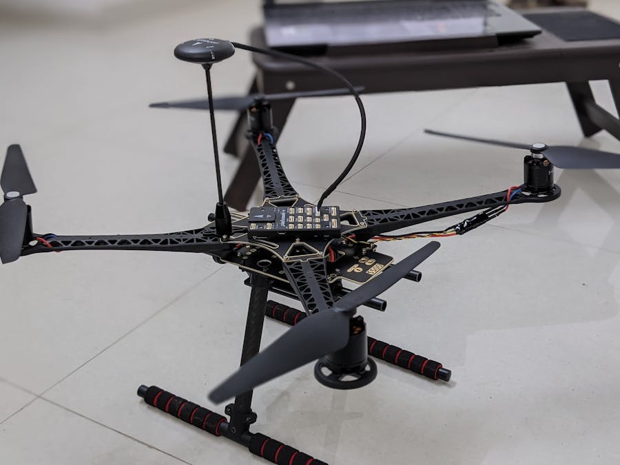
This project intends to deliver the build of the Holybro S500 V2 drone in such a way that all you'll need is the developer kit, a cup of coffee, and our documentation! But yes, we're humans too so if we have missed anything reach us out through the comment section or join the PX4 community for more help.
ASSEMBLING the LANDING GEARInsert the vertical pole in the upper part of the Landing Gear (LG), secure it with a nut and the longest bolt. Put this inside the lower part of the LG and fasten the rest of the nut and bolts.
Allen Key- 2.5mm
RUBBER LOOPS & RODPush the rubber loops inside the small rings and slide the rod inwards.
BATTERY MOUNT SUPPORTSecure the rods to the PDB using bolts.Allen Key- 2mm
BATTERY MOUNTScrew the plate to the brace of the battery mount.Screwdriver- 3mm Phillips screwdriver
SECURING the BATTERY MOUNTFit the battery mount on the 2 rods of the PDB by applying sufficient force.
POWER DISTRIBUTION BOARD to the LANDING GEARAttach the PDB to the LG.Allen Key- 2.5mm
ARMSBolt the 4 arms at the edge of the PDB using bolts.Allen Key- 2mm
MOTOR MOUNTPlace the motor mount on the motor.
MOTORBolt the motor with the mount on the arm of the frame.Allen Key- 2.5mm
ELECTRONIC SPEED CONTROLLERThe following image illustrates the required arrangement of motors on a drone-
1. Counter Clockwise Motors (CCW)- Connect the motor's cables to the ESC color-code wise (Blue to Yellow | Red to Red | Black to Black )2. Clockwise Motors (CW)- Swap one of the cables from the above configuration (Blue to Yellow | Red to Black | Black to Red).
ESC to the 10-10 pin cableConnect the 10 to 10 pin cable (PWM) to the 8*3 2.54mm pitch Horizontal Pin. Join the other end of the ESC's yellow cables to the 8*3 2.54mm pitch Horizontal Pin with respect to the motor's number (Eg- M1, M2, M3, M4).
Connect one end of a 6 pin to the power module on the PDB.
HOLYBRO S500 CENTER PLATEBolt the S500 Center Plate to the arms of the drone (arrowhead in the forward direction).Allen Key- 2mm
GPS MOUNT ASSEMBLYFollow the gif below to complete the GPS mount assembly.Allen Key- 1.5mm
GPSSecure the GPS Mount on the Frame. Using a double side tape stick the GPS on the mount (arrowhead in the forward direction).Allen Key- 2mm
Attach the telemetry antenna and secure it on one end of the drone using tape/zip locks. (Follow the QGC video guide before permanently fixing the telemetry on the drone)
While the arrowhead of the Pixhwak is in the forward direction place it in the center. (Follow the QGC video guide before permanently fixing the Pixhwak on the drone)Connect the following pins to the Pixhwak as follows- 1. Power module to POWER1 2. Telemetry to TELEM1 3. GPS to GPS MODULE 4. Horizontal pin to I/O PWM OUT
PROPELLERSFollow the symbols given on the propellers to lock and unlock them on the drone to their respective CCW & CW motors.
BATTERYSecure the battery under its mount using battery straps/ zip locks.
Finishing up with QGCFinally! the flightJoin the PX4 community at- px4.slack.com


Comments