/*
rear Steering and fpv cam controller with blinker and rear light for cheap 3ch radio trasmitters without any mix functions.
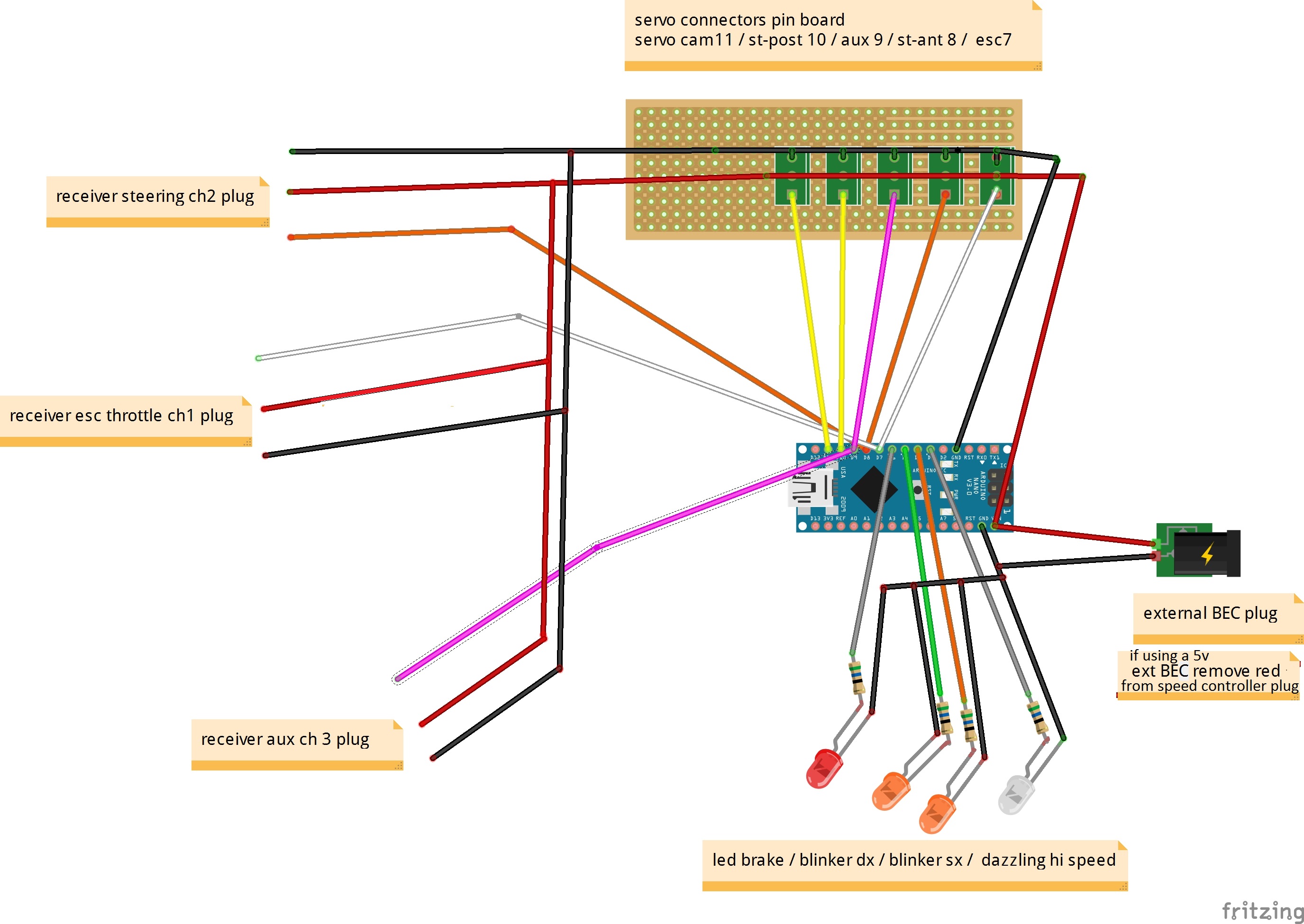
I used an inexpensive nano board v3
the pins used are VIN(+)and GND(-)
you can feed the power from your speed controller bec or by an external bec circuit, check your servo max voltage.
the pins I used are:
pin D7 throttle signal input.
pin D8 front steering input signal. D10 rear steering signal output.
pin D9 aux signal input
pin D4 D5 blinking leds
pin D6 brake rev led light
pin D3 dazzling maxspeed light
pin D10 output steering rear servo
pin D11 output fpv cam rotating servo.
-----------------------------------------
basic setup instructions:
first you must get the best mechanical setup of your front and rear servos, best adjusting link rod best without subtrims and radio adjustements.
the values you find by default should make the controller work quite right away.
however if you want to be sure about your real values about your radio signal inputs check them before starting this sketch.
to check values send by thr str aux channels you must create a new tab in arduino.ide and check your input signals with the serial monitor using this program below
(number 7 is for steering - 8 for throttle - 9 for aux) you must load and launch 3 times, one for each value to check.
int rxpulse;
void setup () {
Serial.begin (9600);
}
void loop () {
rxpulse = pulseIn (7, HIGH); // - 7 to know true front steering signal range, 8 throttle, 9 aux
Serial.println (rxpulse);
you can read the values in the serial monitor by turning the steering wheel of the radio control or moving the throttle.
write the values obtained from your rx and fill the first part of the controller setup, replace the default ones with yours custom values send by transmitter.
-------------------------------------------------- ------
the user driving setup consists of 2 functions:
you can choose how much throttle allow at low speed before the width of the rear servo starts to close (Speedlimit function).
the second function allows you to determine the rear servo width at maximum throttle (Max_gain).
you can choose to close rear steering completely or leave a limitate width available to turn with 4 steering wheels even at maximum speed.
servo cam setup: basically with a 3ch cheap radio aux channel is an on-off interrupt.
aux function 1 set servo cam in fix streight front position and you can set fix angle cam direction to adjust your best visual.
aux function 2 set servo moving by copy steering and you can adjust travel endpoint camsx damdx for max 180 rotation.
also you can adjust centering for moving position in a different visual angle respect function 1 fix position.
both tolerances are used to cutoff vibrations and servo tremors.
led setup:
Blinkpoint: allow value steering travel where direction led start to blink.
Streight: is used to define steering center position just for blinking led light. can be the same of center value of your transmitter but somethimes you must add small corrections if steering center is not set to 1500 or if you have add some center correction.
rearstart: allow to decide reverse value where brake light start on.
----------
troubleshooting:
somethimes it can happen that you exceed with the max values and the steering direction and it result inverted, be careful to find the best suitable max values for your model.
to get the servo reversed you just have to exchange the Postsx Postdx rear steering values and put a sign (-) in front of the Max_gain value
there is a relationship between Slowlimit, Max_gain and rear endpoints, so it can happen that if you lower one value you will have to raise the others or center again wheels centering.
particular model assembly situation give throttle stick in reverse position values, so max thr will be 1000 and min 2000.
in this situation you must check instructions in program line (Gaspulse > Slowlimit) read grey notes about.
inside "loop" in normal RC condition there is nothing really important to modify, just fill all define values numbers and load your setup to nano.
I have written all default values in grey notes, helpful if you wrong some.
however I am sure that it will be easy to understand how all controller works
*/
//----------- signal setup -------------------------------------
#define Neutral 1500 // -- default 1500//minimum throttle forward signal or neutral position
#define Maxspeed 2000 // -- default 2000//maximum throttle forward signal
#define Antsx 1000 // -- default 1000//in front servo signal sx
#define Antdx 2000 // -- default 2000//in front servo signal dx
//----------- rear servo setup -------------------------------
#define Postsx 1000 //-- default 1000//out rear servo sx end point (if inverted with postdx it reverse)
#define Postdx 2000 //-- default 2000//out rear servo dx endpoint (if inverted with postsx it reverse)
#define Center 0 //-- default 0//add or subtract your value to center steering (+- 50 or more)
//--------- user driving setup ------------------------------
#define Max_gain 400 //-- default 400//gain steering reduction width at max throttle (if work reverse add (-) before value)
#define Slowlimit 1600 //-- default 1600//slow forward percentage without endpoint correction
//------------ servo cam setup ------------------------------
#define tolerance 4 //-- default 4//servo cam vibration cutoff
#define front 0 //-- default 0//servo cam front centering in moving aux position
#define Camsx 5 //--default 5// servo cam endpoint sx (reverse with camdx)
#define Camdx 175//-- default 175// servo cam endpoint dx (reverse with camsx)
#define fix 1500 //-- default 1500//servo cam front centering in fix aux position
//-------------led setup ------------------------------------
#define Streight 1500 //-- default 1500//neutral signal steering centered position for blinking arrow light
#define Blinkpoint 200 //-- default 300//steering value where led start to blink.
#define rearstart 1400 //-- default 1300// reverse gear light start at 1300
//----------------------------------------- program part, nothing to do here ---------------
#include <Servo.h>
Servo myservo;
Servo camservo;
#define N_STST 7 // default 7//rear steering vibration cutoff
unsigned int stSt[ N_STST ];
long toStSt = 0;
int inSt = 0;
int Tol = 0;
unsigned int auxpulse;
unsigned int Rxpulse;
unsigned int Gaspulse;
unsigned int Gain;
unsigned int NewPos, OldPos;
unsigned int newloc, oldloc;
unsigned int Centerpos = fix ;
int led1 = 4;
int led2 = 5;
int led3 = 6;
int led4 = 3;
void setup() {
for ( int i=0; i<N_STST; i++ ) stSt[ i ] = 0;
myservo.attach(10); //-- rear servo signal out pin 10
pinMode(8, INPUT); //-- front servo signal in pin 8
pinMode(7, INPUT); //-- throttle signal in pin 7
camservo.attach(11); //-- cam servo out pin 11
pinMode(9, INPUT); //--aux servo signal in pin 9
pinMode(led1, OUTPUT); //--led blinker dx out pin 4
pinMode(led2, OUTPUT); //--led blinker sx out pin 5
pinMode(led3, OUTPUT); //--led retro brake out pin 6
pinMode (led4, OUTPUT); //-- led maxspeed out pin 3
}
void loop(){
auxpulse = pulseIn(9, HIGH);
Gaspulse = pulseIn(7, HIGH);
noInterrupts();
Rxpulse = pulseIn(8, HIGH);
interrupts();
delay(5);
if (Gaspulse > Slowlimit){ //-- default >// if your throttle signal is reversed must change "<"
Gain = map(Gaspulse, Slowlimit, Maxspeed, 0, Max_gain );
NewPos = map(Rxpulse, Antsx, Antdx, (Postsx + Gain), (Postdx - Gain));
}
else{
NewPos = map(Rxpulse, Antsx, Antdx, Postsx, Postdx);
}
if (abs(NewPos - OldPos)> Tol){
OldPos = NewPos;
myservo.write(NewPos + Center);}
//-- led part ----------
if (RXpulse > Streight+Blinkpoint) {digitalWrite(led1, (millis() / 100) % 2); //--default 100// this is led blink speed
}else digitalWrite(led1, LOW);
if (Rxpulse < Streight-Blinkpoint){ digitalWrite(led2, (millis() / 100) % 2); //--default 100// this is led blink speed
} else digitalWrite(led2, LOW);
if (Gaspulse < rearstart){digitalWrite(led3,HIGH);
}else digitalWrite(led3, LOW);
if (Gaspulse > Maxspeed-100){digitalWrite(led4,HIGH); //-- default 100// higher values start light before maxspeed limit
}else digitalWrite(led4, LOW);
//-- aux cam part ----------
if (auxpulse > 1600){//--default > 1600// define and change aux position
camservo.write(fix);
delay (4);
}else {
newloc = map(pulseIn(8, HIGH),Antsx,Antdx,Camsx,Camdx);
if(abs(newloc - oldloc) > tolerance){
oldloc = newloc;
camservo.write(newloc + front);
}
}
}


_3u05Tpwasz.png?auto=compress%2Cformat&w=40&h=40&fit=fillmax&bg=fff&dpr=2)
Comments