


Add the ability to have your printer shut itself off after a print completes. In this guide, I build and explain how my Auto Shutdown Board works. It's a small supplementary board, powered by another microcontroller, that works independently from the main board.
Features:- Printer works without Auto Shutdown board powered
- Turn on before OR mid print
- Non contact sensor
- Programmable
- Waits for hotend to cool
This is more down the ally of an electronics enthusiast or someone learning to make their own circuit boards rather than the "I just need it to work" user. If you fall in the ladder, please don't bring up Octoprint's shutdown plugin. Even that has its pitfalls as you need a dedicated single board computer for the OS, now you depend on the network connection, and you need an external device to navigate through the UI. If you do happen to be interested in this and you have a Raspberry Pi setup, this won't interfere with it.
How it WorksPower on the board anytime before or during a print. Once the print finishes, the X carriage returns home and triggers a secondary sensor. A microcontroller reads the conditioned sensor signal. If triggered, the microcontroller waits 6 minutes until it turns on a relay to cut the power. The user has the ability to cancel the countdown by moving the X carriage out of its home position.
Bill of MaterialsComponents:
- ATtiny13a (DIP8)
- LM2904 OP Amp (DIP8)
- AH3505 Linear Hall Effect Sensor (TO-92UA)
- 5V Relay
- ZTX458 PNP Transistor (TO-92a)
- Diode 1N4001
- Push Button
- 1x Resistor 1kΩ
- 2x Resistor 390Ω
- 10k Trimpot
- 8mm x 2mm Magnet
- 2x DIP8 Socket
- 2x 3 Pin Screw Terminal
- 3x JST-XH-02 Male Connector
- 3x JST-XH-02 Female Connector
- 1x JST-XH-03 Male Connector
- 1x JST-XH-03 Female Connector
- JST-XH Terminals
- 50mm x 70mm Perfboard
- Wires
Tools:
Software:
Operating LogicThe purpose of having that microcontroller is to add time and logic. This can work with just some form of switch that controls a relay, but you must be aware that the hotend fan fill turn off as well. If you have printed parts mounted on the hotend, you run the risk of melting them. For this reason, I needed to add time into the equation.
After a test run, it took about 6 minutes for my hotend to drop from 240°C to 60°C. I determined the lower temperature bound by making sure I was below the glass transition temperature, Tg, of the plastic around my hotend.
- PLA: Tg = 50°C
- PETG: Tg = 70°C
- ABS: Tg = 100°C
Tip: The bed temperature for your filament is the glass transition temperature. I waited until it hit 10°C below my PETG's Tg, which took 6 minutes as I mentioned before. The microcontroller waits 6 minutes, but the code continuously checks whether the sensor is still triggered during these 6 minutes. This allows the user to cancel the operation if they move the X carriage out of the trigger distance.
The microcontroller follows the logic shown in the flowchart above. You can view the code equivalent of this logic in the file supplied at the bottom of the guide.
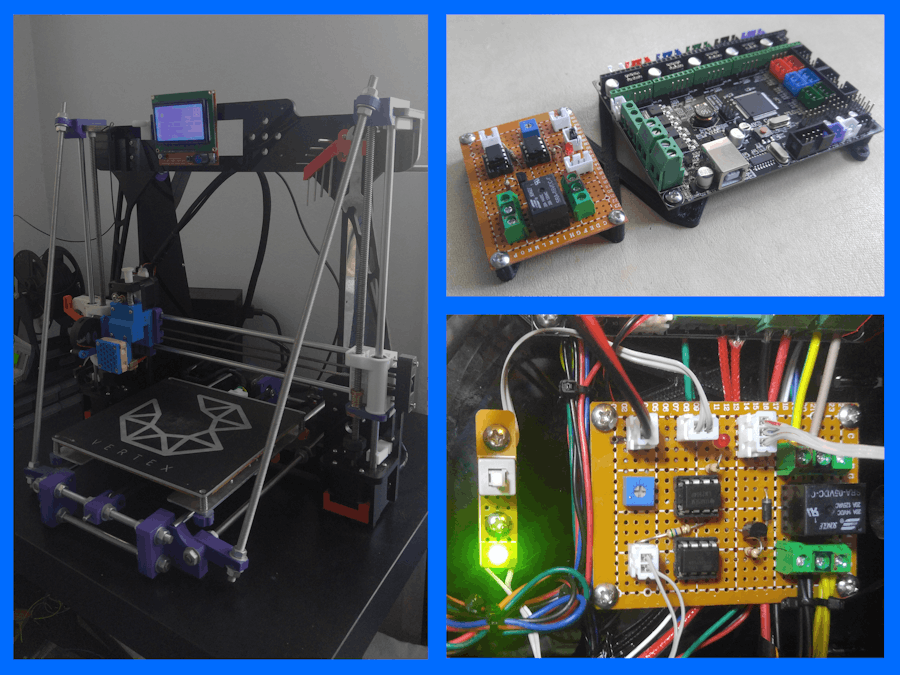
HardwareThere are 3 boards (scroll through the images below):
- 1: Large Electronics Board
- 2: Sensor Board
- 3: Power Switch Board
The power switch board is separate from the main board so it can be mounted on a front panel next to the main display. I talk more about this in the "Mounting" section of the guide.
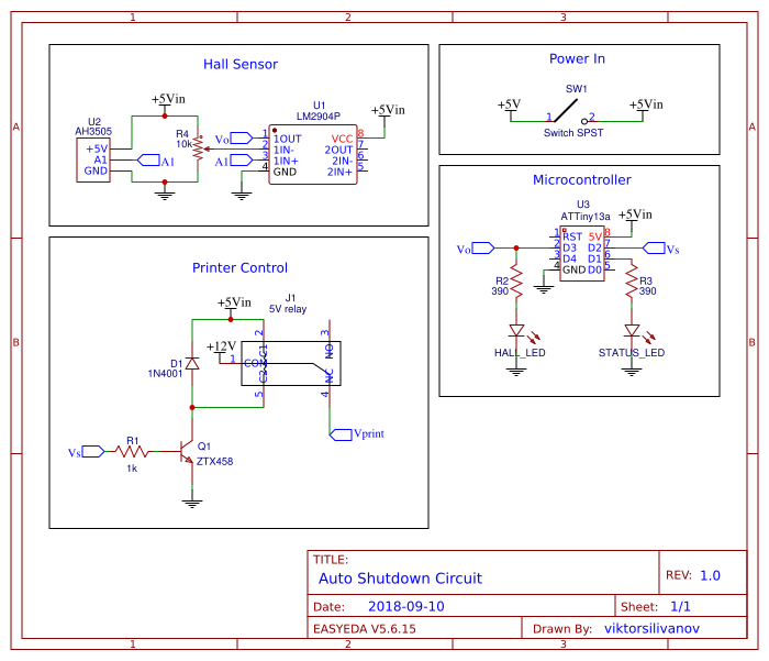
There are 3 main "blocks" that comprise the large board.
The first block is everything involved with the sensor. I could have used any sensor/switch. The ever so popular mechanical microswitch would have been the simplest choice, and would have cut down on the circuitry, but those endstops suffer from mechanical wear and they're noisy. There's an elegance to the silent, non-contact magnetic sensor.
The magnetic sensor I used is called a Linear Hall Effect Sensor. It idles at 1/2 of the voltage that it's supplied. If Vcc = 5V, and Vee = 0V, then Vidle = 2.5V. Once a magnetic field nears the sensor, the output voltage rises from 2.5V to 5V linearly. With an opposite magnetic field, the output voltage falls from 2.5V to 0V linearly. If an Op Amp is wired in the configuration below, we can use it as a comparator. This means that it looks at 2 voltages, and when the non-inverting (+) pin is higher than the inverting pin (-), then it outputs high.
The two resistors set the threshold voltage. If they're equal, the threshold is Vcc/2. This is not desirable as the Hall sensor idles at Vcc/2, so I added a potentiometer in place of the resistors to vary the threshold voltage. This translates to varying what the trigger distance is when the magnet nears.
The second block is just the microcontroller. This is where logic is applied to the signal from the Op Amp. It controls the status LED and the third block. The code is discussed toward the end where I discuss programming the ATtiny.
The third block is the power portion of the board. This consists of a PNP transistor that drives the relay. Don't forget a flyback diode to stop back EMF from the magnetic field in the relay collapsing and causing a voltage spike. Without this diode, your transistor will die shortly or in due time. The connectors I used are rated for 10A, which is not quite where I want them to be. A comfortable rating is between 15-20A if you're using a 12V system with a heated bed.
Schematics & LayoutThe best advice I can offer when laying out the components on the perfboard is to constantly reference the schematics and check continuity with your multimeter regularly. Also, you could really use any NPN BJT that is in spec. I just happened to have spare ZTX458's, but I've noticed that they're a little exotic. You really just need to drive 5V through the coil at the current listed in the Relay's datasheet.
Unless you have a vision as to how you can change the layout for your own needs, it's likely easiest to follow the one I have. The underside of my board turned out to be embarrassingly bad. I know for a fact that the way I made my connections is far from efficient, and all those perfboard pros can outdo me blindfolded, so I can't provide guidance for your connections.
Note that the schematics do NOT show the location of the connectors. You would need connectors at the following locations:
- Power IN (2 pin JST-XH)
- Power Switch (2 pin JST-XH)
- Status LED (2 pin JST-XH)
- Hall Effect Sensor (3 pin JST-XH)
- 12Vin (3 pin screw terminal)
- 12Vout (3 pin screw terminal)
Along with having the male JST connectors on board, you'll need to create custom wires with female JST connectors. I followed this video until I got the hang of it. Best advice I found was that there are 2 sets of wings. The longer ones at the end bite into the insulation; whereas, the shorter ones in the middle grab the exposed stranded wire. For my wires, I mostly used salvaged cables on old IDE connectors from some PCs I found in the trash. They work great!
You can choose to mount it as you wish. My end goal is to have all my electronics mounted in a box, but I'm not ready to do that just yet. I modeled a temporary mounting solution for my Anet A8 in Fusion 360, which very few of you will need, but it doesn't hurt to provide it.
I provided the files below anyway. Note that I had to expand the mounting holes on the perfboard to 3mm using my knock off dremel. Any rotary tool, hand drill, or drill press will do. Alternatively, you can download the STL here.
I temporarily taped down my Hall sensor to my X axis endstop. Later I will print a mount for both my main endstop and the Hall sensor. Luckily, since this is a non contact sensor, I don't have any mechanical movement, so it has been in one spot.
Finally, mount some of those circular magnets onto your carriage. The way my carriage was built allowed me simply stick them onto the extruder. You may need to model and print your own mount for the magnet.
Programming the ATtinyThe code is provided at the bottom of the guide. There's really not much to it. Avoiding those pesky delay() functions allowed me to not halt the processor, which gives the user the chance to abort the shutdown operation even after the sensor has been triggered. The only portion I advise modifying for your needs is the time located in the global variables.
float time = 6.0; // Time (in minutes) to shut down. Modify this if neededKeep in mind that this is an ATtiny, so you'll need to upload code via a serial programmer such as a USBasp or another Arduino as an ISP. If you're not sure how to do this, fear not. I have a full guide on how to make a programmer board for these ATtinys.
To trigger the sensor, we need to make sure the carriage actually moves towards it. Add the lines below through your slicer to the ending script. As I use Simplify3D, I found that in Scripts > Ending Scripts.
M104 S0 			; turn off extruder
M140 S0 			; turn off bed
G1 E-1 F300			; retract the filament a bit
G28 X0			        ; home X
M84 			        ; disable all motors
M104			        ; disable extruder motor
M107 			        ; shut off fan
G1 Y210 F9000			; move bed forward
M84 ; disable all motorsAfter testing it for some weeks, it works better than I expected. I do not have any misreads, no parts burning out, or relay problems. I was a bit worried about my connectors being rated for a somewhat low current, but they've been holding up well. The logic in the code has not let me down, as I've taken advantage of the back out option. Sometimes I forget that the board is on and the printer shuts off haha. I'm always pleasantly surprised that it works. If you make this or some kind of improved version/derivative, please share it with me!


Comments