Brief Abstract about my project:-
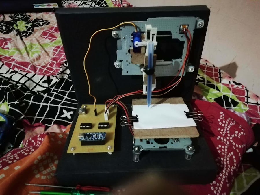
A CNC machine or computer numeric machine is designed to control various machinery functions using computer programs. In this project, the machine is made such that the code made for it can be used to draw the outcome of that code. This concept is used to make logos, drawings, and other artwork in real less time. Portraits and sketches can be made like an artist's masterpiece.
All we have to do is make a code of that picture. Yes! So what we are doing in this project is that firstly, we need a picture in png. or jpeg. form and that picture's outline is converted into g-code (this can be done with the help of various apps that offers to do so). So the g-code is a program that will be used to run the CNC machine to draw that code's picture. We have already prepared some g- codes for our CNC machine, which includes the outline of a tattoo. We are using plain white sheets as a screen where the pen inserted in a machine can draw. The movement of this pen is controlled by the motors used for the X, Y, and Z-axis (where these axes are instructed through the G- code). We are using an 8mm motor for the X and Y axis and one servo motor for Z-axis.
Step 1: How Its Work
In this project, we need some basic equipment like a laptop, cables and some software. This machine can draw any 2D figure by converting any 2D image or file into G-code(geometrical-code).
G-code can be made by using the software as we need Inkscape for converting our figure into the 2D G-code.you can also use other software to make G-code like Mak3Mill, CAmotics, etc. We also need G-code sender software, in this project, I am using processing-3 software to print a G-code on the board, also you can use another software like Google G-sender.
Step 2: Stuff Required- 4 Pin Relimate male/female connector =2
- USB to type B USB cable =1
Step 3: Circuit Diagram
Step 4: How to Make It- We will connect all the connectors on the PCB.
- We Soldered all the connectors in a PC.
- We connect D2, D3, D4, D5 Pin of Arduino to Pin no 2, 7, 10, 15 of IC1 And connect D8, D9, D10, D11 pin of Arduino to pin no 2, 7, 10, 15 of IC2.
- Connect pin no 1, 8, 9, 16 of both IC to the +5V DC (Means connect the positive pin of USB.
- Connect pin no 4, 5, 12, 13 of both IC to the Ground pin of IC and Arduino.
- Connect the D6 pin of Arduino to the Servo signal pin.
- Connect the servo +ve and –ve wire to the USB +ve & -ve pin.
- Solder the Stepper Motor with connector wire.
- Connect (IC1) Pin no 3 & 6 to stepper B & D and Pin no 11 & 14 to A & C.
- Connect (IC2) Pin no 3 & 6 to stepper D & B and Pin no 11 & 14 to C & A.
- Check all the wiring is correct and test the circuit.
Step 5: Upload Code
- Download the attached Arduino sketch. Connect Arduino to PC with the USB cable. Upload sketch.
- Now open the Processing Software and compile gcode_executer_code.
- Now add the G-code file to the software and then run it, your machine is running.
Step 6: Downloading Link 


Comments