


Hardware components | ||||||
| × | 1 | ||||
| × | 1 | ||||
| × | 4 | ||||
| × | 1 | ||||
| × | 1 | ||||
| × | 2 | ||||
| × | 1 | ||||
Software apps and online services | ||||||
 |
| |||||
| ||||||
Hand tools and fabrication machines | ||||||
 |
| |||||
 |
| |||||
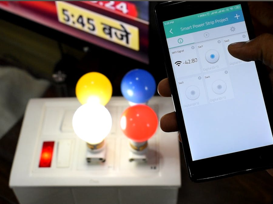
Here is the project which lets you turn on and off devices connected on power strip wirelessly using the Internet. You can also automate the daily repetitive task with scheduling feature, so the appliance will automatically be turned on and off on set timings.
Pre-Requisite: We need Arduino IDE software installed in PC/laptop and configure Wemos D1 board to IDE for programming.
Arduino IDE Installation and Wemos/ESP8266 Configuration1) Arduino IDE setup:Follow the Arduino official link below to install Arduino IDE on your respective OS:
On Windows -> https://www.arduino.cc/en/Guide/Windows
On Linux -> https://www.arduino.cc/en/Guide/Linux
On Mac -> https://www.arduino.cc/en/Guide/MacOSX
For Windows and Mac, it is pretty straight forward to install, no major problem faced during installation. But Linux user especially beginners find some issue regarding Arduino installation of which most common serial upload error issue ("avrdude: ser_open(): can't open device" ) during the first time installation. So, I recorded a video which you may follow:
2) Configure Wemos D1 board to Arduino software: Actually, Wemos D1 board is made using the ESP8266 chip. So, to add Wemos to boards list we will have to follow steps given on esp8266 GitHub link: https://github.com/esp8266/Arduino
WARNING:This project includes work around HIGH VOLTAGE 230V and HIGH CURRENT 5A. Electricity is dangerous so please be careful!!! You must have at least basic knowledge of Electricity or electrical wiring otherwise attempt this project under the supervision of an electrical expert. I will not be responsible for any damage caused due to improper handling.
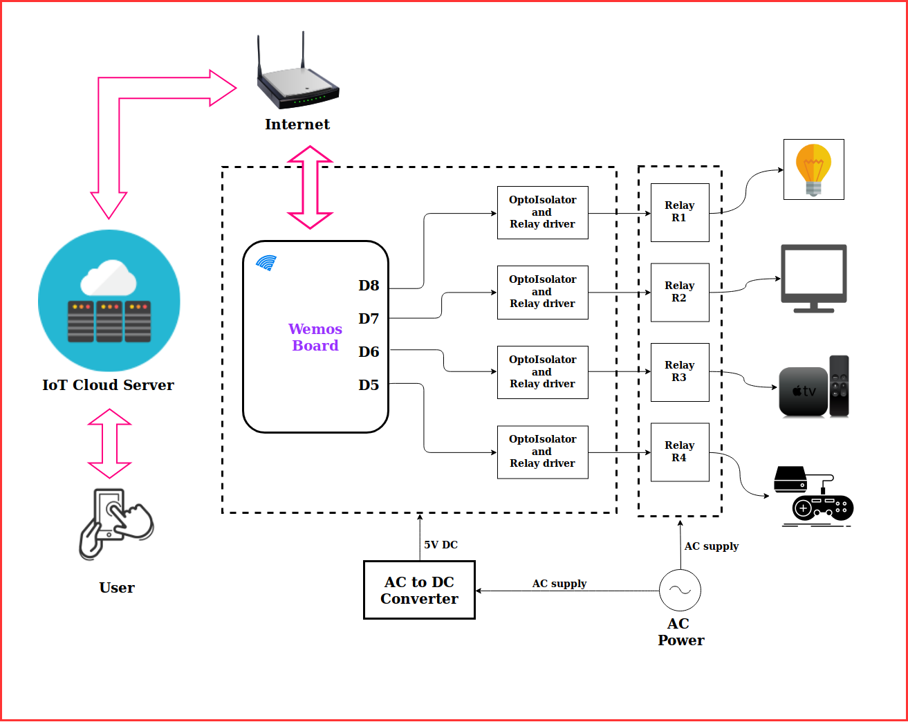
Control Board DetailsControl board is equipped with most familiar ESP8266 based Wemos d1 microcontroller and 4 Relay to operate 4 Electrical devices. No headache of jumper wires and separate power adapter. This board is equipped with onboard AC(230V AC) to DC power module (5W and DC5V).
Let us check out the details of pin connection going from Wemos D1 to the various part on the baseboard and other breakouts which are available.
Other Breakouts in case if you are interested to experiment i.e want to add some sensor like temperature, humidity or security PIR motion sensor.
So, now let us first check the working of control board before proceeding for the next steps. For this just copy and paste code to Arduino IDE provided in code section -> SmartPowerStrip_testcode.ino
Verify and upload it to the control board by selecting proper board and configuration as shown in the video ->
Cloud Server Setup and Testing:For this project, I have used Cayenne IoT Cloud server to operate the device. To create an account visit link: https://cayenne.mydevices.com
For this step will use the final code of the project given in code section-> SmartPowerStripv2_finalcode.ino
Below video shows the process to setup and configures Cayenne cloud for smart power strip project:
You can also use the mobile app to operate the device. Click here to download Android app
Electrical Connection & Packaging :Below is the basic wiring connection to control four Electrical appliances (here 4 Light Bulb for demo). You can go with wiring convention as followed in your countries. I have shown below the most basic configuration.
Case 1: Neutral is given to all appliances while Live is connected via Switch.
Case 2: Live is given to all appliances while Neutral is connected via Switch
Packaging:Now, let's proceed for packaging.Components need for further steps are (all components purchased from the local electrical shop) :
1. Electrical Switch box
2. Electrical Socket 3pin (you can also use 2 pins)
3. Live/Phase indicator
4. Plug wire 2 pin
5. Electrical Switch 2way (optional, needed only if interested to control device from the physical switch also)
Using a screwdriver and wire cutter make below electrical connection with the control board.
Connection without 2Way switch:
Connection with 2Way Switch:The image below shows the basic wiring technique for 2 way connection.
So, to demonstrate I will show connections with the first two relays. But you can try for all 4 relays.
Thanks!!


Comments