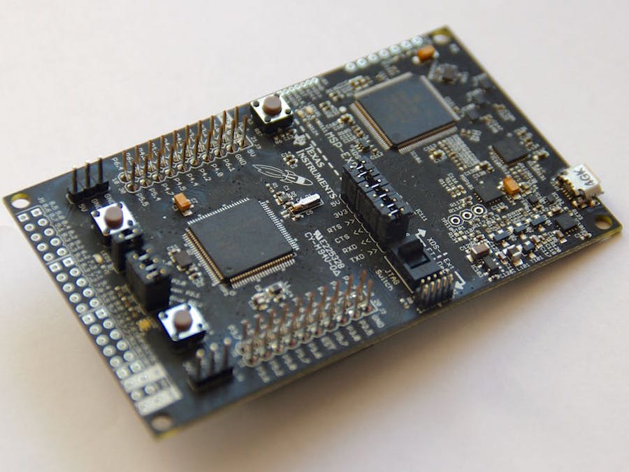
The MSP432 LaunchPad features the MSP432P401R with 256 KB of Flash and 64 KB of RAM running at 48 MHz. As always, the programmer-debugger connects through USB.
The board also features one red LED and one RGB LED, one reset plus two user-buttons, and connectors for a 40-pin BoosterPack.
Energia IDE and Galaxia LibraryThe Arduino-compatible IDE or integrated development environment is called Energia. However, Energia comes with a major new release for this board: Energia MT.
Energia MT stands for Energia Multi-Tasking and is based on Texas Instruments RTOS, aka. Real Time Operating System. Real-time means each task is completed within a determined period of time, and RTOS is an operating system built on it.
I've developed libraries which encapsulate the RTOS elements into classes with a consistent and minimal set of functions. The goal is to provide libraries with the same ease of use as the standard classes (e.g. SPI, I²C, Serial) provided by the Wiring / Arduino framework. All the libraries are bundled in one single package called Galaxia, included in the Energia distribution.
The goal of the project is to blink the each of the three colours, red, green and blue, of the RGB LED at different paces.
Managing the 3 LEDs in one single sketch is doable, but difficult.
With Energia MT, each LED is managed by a different task.
First Solution: Three delay()-Based TasksThe Energia distribution comes with the MultiBlink example. The full project is attached as a ZIP file.
Each LED is managed by a different task defined in a separate sketch. Each sketch includes the standard setup...() and loop...() functions.
So we have 3 different sketches, one per LED:
- RedLed.ino for the red LED with setupRedLed() and loopRedLed().
#undef LED
#define LED RED_LED

void setupRedLed() {
  // initialize the digital pin as an output.
  pinMode(LED, OUTPUT);
}

// the loop routine runs over and over again forever as a task.
void loopRedLed() {
  digitalWrite(LED, HIGH);   // turn the LED on (HIGH is the voltage level)
  delay(100);               // wait for 1/10th of a second
  digitalWrite(LED, LOW);    // turn the LED off by making the voltage LOW
  delay(100);               // wait for 1/10th of a second
}
- GreenLed.ino for the green LED with setupGreenLed() and loopGreenLed().
#undef LED
#define LED GREEN_LED

void setupGreenLed() {
  // initialize the digital pin as an output.
  pinMode(LED, OUTPUT);
}

// the loop routine runs over and over again forever as a task.
void loopGreenLed() {
  digitalWrite(LED, HIGH);   // turn the LED on (HIGH is the voltage level)
  delay(333);               // wait for 1/3rd of a second
  digitalWrite(LED, LOW);    // turn the LED off by making the voltage LOW
  delay(333);               // wait for 1/3rd of a second
}
- BlueLed.ino for the blueLED with setupBlueLed() and loopBlueLed().
#undef LED
#define LED RED_LED

void setupRedLed() {
  // initialize the digital pin as an output.
  pinMode(LED, OUTPUT);
}

// the loop routine runs over and over again forever as a task.
void loopRedLed() {
  digitalWrite(LED, HIGH);   // turn the LED on (HIGH is the voltage level)
  delay(500);               // wait for half a second
  digitalWrite(LED, LOW);    // turn the LED off by making the voltage LOW
  delay(500);               // wait for half a second
}
The last sketch MultiBlink.ino is empty. It only provides the name for the project.
When a task runs and executes delay(), the tasks pauses and the handle returns to the scheduler, so other tasks can be executed.
Second solution: Three Clocks with Galaxia LibraryThis implement relies on clocks and illustrates a radically different approach to the previous solution. There is one single sketch and three clocks, one per colour. The full project is attached as a ZIP file.
The preliminary part of the sketch is very standard, with includes, a structure for the LED, variables for each colour of the RGB LED.
// Core library for code-sense - IDE-based
#   include "Energia.h"

// Include application, user and local libraries
#include "rtosGlobals.h"
#include "Clock.h"

// Prototypes

// Define variables and constants
struct LED_t {
    uint8_t status;
    uint8_t pin;
};

LED_t ledR = { 0, RED_LED };
LED_t ledG = { 0, GREEN_LED };
LED_t ledB = { 0, BLUE_LED };
Then come three blinking functions, one for each colour of the RGB LED.
// Functions
void clockFunctionR()
{
    ledR.status = 1 - ledR.status;
    digitalWrite(ledR.pin, ledR.status);
}

void clockFunctionG()
{
    ledG.status = 1 - ledG.status;
    digitalWrite(ledG.pin, ledG.status);
}

void clockFunctionB()
{
    ledB.status = 1 - ledB.status;
    digitalWrite(ledB.pin, ledB.status);
}
Instead of having 3 tasks, the main part of the sketch contains three clocks. Each clock calls a dedicated function to manage one colour of the RGB LED.
// Define variables and constants
Clock myClockR;
Clock myClockG;
Clock myClockB;
The setup() function initialises the three pins as OUTPUT, the three clocks. Note the function called by the Clock needs to be void clockFunction().
// Setup
void setup()
{
    pinMode(RED_LED, OUTPUT);
    pinMode(GREEN_LED, OUTPUT);
    pinMode(BLUE_LED, OUTPUT);


    myClockR.begin(clockFunctionR, 1000, 100); // 1000 ms = 1 s
    myClockG.begin(clockFunctionG, 1000, 333); // 1000 ms = 1 s
    myClockB.begin(clockFunctionB, 1000, 500); // 1000 ms = 1 s

    myClockR.start();
    myClockG.start();
    myClockB.start();
}
Two periods are defined:
- the first one is the initial start delay,
- and the second is the repetitive period.
Both are stated in ms. If the initial start delay is equal to 0, the clock starts immediately. If the repetitive period is equal to 0, the clock runs only once (one-shot timer).
In this example, the clocks start running after 1 second, and call the respective functions every 100, 333 or 500 ms.
Finally, each clock is launched.
The loop() function is empty!
// Loop
void loop()
{
}
Now, compare those two implementations. Both do exactly the same.
Which one do you prefer?


Comments