#include "driverlib.h"
//Timer
int Timer = 1000;
//Voltage variable
int voltage;
int voltage2;
char low[10] = "Low V";
char med[10] = "Med V";
char high[10] = "High V";
char armone[10] = "Arm 1";
char armtwo[10] = "Arm 2";
//LED pin setup
#define Blue BIT3
#define Green BIT4
#define Red BIT5
//LED functions
void RedLED1();
void GreenLED1();
void BlueLED1();
void RedLED2();
void GreenLED2();
void BlueLED2();
void ArmOne();
void ArmTwo();
int v = 0;
int w = 0;
void main (void)
{
volatile uint16_t i;
//Stop Watchdog Timer
WDT_A_hold(WDT_A_BASE);
//Enable A/D channel A0
GPIO_setAsPeripheralModuleFunctionInputPin(GPIO_PORT_P6,
GPIO_PIN1
);
GPIO_setAsPeripheralModuleFunctionInputPin(GPIO_PORT_P6,
GPIO_PIN6
);
//LED 1
GPIO_setAsOutputPin(GPIO_PORT_P1,
GPIO_PIN5);
GPIO_setAsOutputPin(GPIO_PORT_P1,
GPIO_PIN4);
GPIO_setAsOutputPin(GPIO_PORT_P1,
GPIO_PIN3);
//LED 2
GPIO_setAsOutputPin(GPIO_PORT_P1,
GPIO_PIN2);
GPIO_setAsOutputPin(GPIO_PORT_P4,
GPIO_PIN3);
GPIO_setAsOutputPin(GPIO_PORT_P4,
GPIO_PIN0);
//RS232 Connection SetUp
P3SEL |= BIT3+BIT4; // P3.3,4 = USCI_A0 TXD/RXD
UCA0CTL1 |= UCSWRST; // **Put state machine in reset**
UCA0CTL1 |= UCSSEL_2; // SMCLK
UCA0BR0 = 9; // 1MHz 115200 (see User's Guide)
UCA0BR1 = 0; // 1MHz 115200
UCA0MCTL |= UCBRS_1 + UCBRF_0; // Modulation UCBRSx=1, UCBRFx=0
UCA0CTL1 &= ~UCSWRST; // **Initialize USCI state machine**
UCA0IE |= UCRXIE; // Enable USCI_A0 RX interrupt
UCA0BR0 = 104; // 1MHz SMCLK, 9600 bits/second (baud)
UCA0BR1 = 0; // 1MHz SMCLK, 9600 baud
UCA0MCTL = UCBRS1; // 2nd Modulation stage = 1
UCA0CTL1 &= ~UCSWRST; // Initialize USCI state machine
//Initialize the ADC12_A Module
/*
* Base address of ADC12_A Module
* Use internal ADC12_A bit as sample/hold signal to start conversion
* USE MODOSC 5MHZ Digital Oscillator as clock source
* Use default clock divider of 1
*/
ADC12_A_init(ADC12_A_BASE,
ADC12_A_SAMPLEHOLDSOURCE_SC,
ADC12_A_CLOCKSOURCE_ADC12OSC,
ADC12_A_CLOCKDIVIDER_1);
ADC12_A_enable(ADC12_A_BASE);
/*
* Base address of ADC12_A Module
* For memory buffers 0-7 sample/hold for 64 clock cycles
* For memory buffers 8-15 sample/hold for 4 clock cycles (default)
* Disable Multiple Sampling
*/
ADC12_A_setupSamplingTimer(ADC12_A_BASE,
ADC12_A_CYCLEHOLD_64_CYCLES,
ADC12_A_CYCLEHOLD_4_CYCLES,
ADC12_A_MULTIPLESAMPLESDISABLE);
//Configure Memory Buffer
/*
* Base address of the ADC12_A Module
* Configure memory buffer 0
* Map input A0 to memory buffer 0
* Vr+ = Vref+ (int)
* Vr- = AVss
* Memory buffer 0 is not the end of a sequence
*/
ADC12_A_configureMemoryParam param = {0};
param.memoryBufferControlIndex = ADC12_A_MEMORY_0;
param.inputSourceSelect = ADC12_A_INPUT_A0;
param.memoryBufferControlIndex = ADC12_A_MEMORY_1;
param.inputSourceSelect = ADC12_A_INPUT_A6;
param.positiveRefVoltageSourceSelect = ADC12_A_VREFPOS_INT;
param.negativeRefVoltageSourceSelect = ADC12_A_VREFNEG_AVSS;
param.endOfSequence = ADC12_A_NOTENDOFSEQUENCE;
ADC12_A_configureMemory(ADC12_A_BASE ,¶m);
//Configure internal reference
//If ref generator busy, WAIT
while ( REF_ACTIVE == Ref_isRefGenBusy(REF_BASE) ) ;
//Select internal ref = 1.5V
Ref_setReferenceVoltage(REF_BASE,
REF_VREF1_5V);
//Internal Reference ON
Ref_enableReferenceVoltage(REF_BASE);
//Delay (~75us) for Ref to settle
__delay_cycles(75);
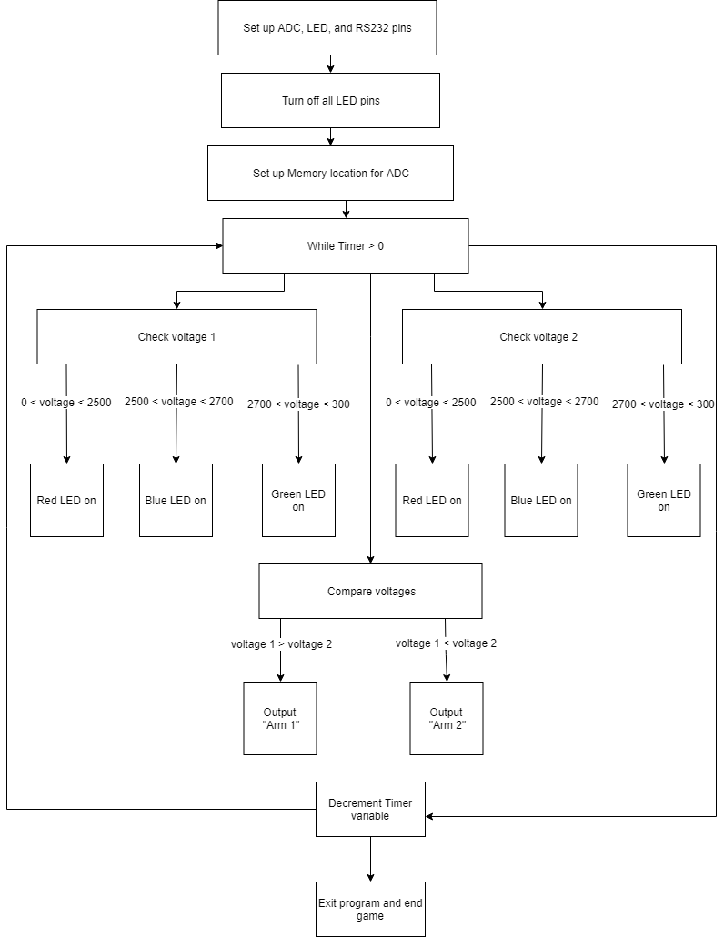
while (0 < Timer)
{
//Enable/Start first sampling and conversion cycle
/*
* Base address of ADC12_A Module
* Start the conversion into memory buffer 0
* Use the single-channel, single-conversion mode
*/
ADC12_A_startConversion(ADC12_A_BASE,
ADC12_A_MEMORY_0,
ADC12_A_SINGLECHANNEL);
ADC12_A_startConversion(ADC12_A_BASE,
ADC12_A_MEMORY_1,
ADC12_A_SINGLECHANNEL);
//Poll for interrupt on memory buffer 0
while (!ADC12_A_getInterruptStatus(ADC12_A_BASE,
ADC12IFG0)) ;
voltage = (unsigned int) ADC12MEM0;
while (!ADC12_A_getInterruptStatus(ADC12_A_BASE,
ADC12IFG1)) ;
voltage2 = (unsigned int) ADC12MEM1;
//Arm 1 LED controll
if(0 < voltage && voltage < 2500)
{
RedLED1();
}
if(2500 < voltage && voltage < 2700)
{
BlueLED1();
}
if(2700 < voltage && voltage < 3000)
{
GreenLED1();
}
//Arm2 LED controll
if(0 < voltage2 && voltage2 < 2500)
{
RedLED2();
}
if(2500 < voltage2 && voltage2 < 2700)
{
BlueLED2();
}
if(2700 < voltage2 && voltage2 < 3000)
{
GreenLED2();
}
if(voltage > voltage2)
{
v = 0;
w = 0;
ArmOne();
}
else
{
v = 0;
w = 0;
ArmTwo();
}
Timer--;
//SET BREAKPOINT HERE
__no_operation();
}
}
void RedLED1()
{
GPIO_setOutputLowOnPin(GPIO_PORT_P1,
GPIO_PIN5);
GPIO_setOutputHighOnPin(GPIO_PORT_P1,
GPIO_PIN4);
GPIO_setOutputHighOnPin(GPIO_PORT_P1,
GPIO_PIN3);
GPIO_setOutputHighOnPin(GPIO_PORT_P1,
GPIO_PIN2);
GPIO_setOutputHighOnPin(GPIO_PORT_P4,
GPIO_PIN3);
GPIO_setOutputHighOnPin(GPIO_PORT_P4,
GPIO_PIN0);
}
void GreenLED1()
{
GPIO_setOutputHighOnPin(GPIO_PORT_P1,
GPIO_PIN5);
GPIO_setOutputLowOnPin(GPIO_PORT_P1,
GPIO_PIN4);
GPIO_setOutputHighOnPin(GPIO_PORT_P1,
GPIO_PIN3);
GPIO_setOutputHighOnPin(GPIO_PORT_P1,
GPIO_PIN2);
GPIO_setOutputHighOnPin(GPIO_PORT_P4,
GPIO_PIN3);
GPIO_setOutputHighOnPin(GPIO_PORT_P4,
GPIO_PIN0);
}
void BlueLED1()
{
GPIO_setOutputHighOnPin(GPIO_PORT_P1,
GPIO_PIN5);
GPIO_setOutputHighOnPin(GPIO_PORT_P1,
GPIO_PIN4);
GPIO_setOutputLowOnPin(GPIO_PORT_P1,
GPIO_PIN3);
GPIO_setOutputHighOnPin(GPIO_PORT_P1,
GPIO_PIN2);
GPIO_setOutputHighOnPin(GPIO_PORT_P4,
GPIO_PIN3);
GPIO_setOutputHighOnPin(GPIO_PORT_P4,
GPIO_PIN0);
}
void RedLED2()
{
GPIO_setOutputHighOnPin(GPIO_PORT_P1,
GPIO_PIN5);
GPIO_setOutputHighOnPin(GPIO_PORT_P1,
GPIO_PIN4);
GPIO_setOutputLowOnPin(GPIO_PORT_P1,
GPIO_PIN3);
GPIO_setOutputHighOnPin(GPIO_PORT_P1,
GPIO_PIN2);
GPIO_setOutputHighOnPin(GPIO_PORT_P4,
GPIO_PIN3);
GPIO_setOutputHighOnPin(GPIO_PORT_P4,
GPIO_PIN0);
}
void GreenLED2()
{
GPIO_setOutputHighOnPin(GPIO_PORT_P1,
GPIO_PIN5);
GPIO_setOutputHighOnPin(GPIO_PORT_P1,
GPIO_PIN4);
GPIO_setOutputHighOnPin(GPIO_PORT_P1,
GPIO_PIN3);
GPIO_setOutputHighOnPin(GPIO_PORT_P1,
GPIO_PIN2);
GPIO_setOutputLowOnPin(GPIO_PORT_P4,
GPIO_PIN3);
GPIO_setOutputHighOnPin(GPIO_PORT_P4,
GPIO_PIN0);
}
void BlueLED2()
{
GPIO_setOutputHighOnPin(GPIO_PORT_P1,
GPIO_PIN5);
GPIO_setOutputHighOnPin(GPIO_PORT_P1,
GPIO_PIN4);
GPIO_setOutputHighOnPin(GPIO_PORT_P1,
GPIO_PIN3);
GPIO_setOutputHighOnPin(GPIO_PORT_P1,
GPIO_PIN2);
GPIO_setOutputHighOnPin(GPIO_PORT_P4,
GPIO_PIN3);
GPIO_setOutputLowOnPin(GPIO_PORT_P4,
GPIO_PIN0);
}
void ArmOne()
{
while(v < 10)
{
UCA0TXBUF = armone[v]; // transmit single character
v++;
__delay_cycles(1000);
}
}
void ArmTwo()
{
while(w < 10)
{
UCA0TXBUF = armtwo[w]; // transmit single character
w++;
__delay_cycles(1000);
}
}


_3u05Tpwasz.png?auto=compress%2Cformat&w=40&h=40&fit=fillmax&bg=fff&dpr=2)

Comments