


Hardware components | ||||||
| × | 1 | ||||
| × | 1 | ||||
| × | 1 | ||||
Software apps and online services | ||||||
 |
| |||||
Hand tools and fabrication machines | ||||||
 |
| |||||
It is a robot kit which is assembled with IR line follower sensor. IR follower sensor contains IR Receiver and IR Transmitter and it detects reflection of light. If the IR sensor detects black surface, less reflection of light occurs as black surface absorbs light. There is no reflected light ray so it will sense that there is obstacle. Robot kit then stops moving.
While if IR sensor detects white surface, more reflection of light occurs as white surface reflects light. The reflected light ray will be received by IR Receiver and voltage changes. There is no obstacle so the robot kit will keep moving.
Below are every component you need for the project. Instead circuito, you should have refer the components below. You can refer to circuito.io for a clear image of the components and wiring.
What Do You Need?Arduino Uno x1
Breadboard x1
Jumper Wire M/M x1 set
Jumper Wire F/M x1 set
IR Line Track Follower Sensor TCRT5000 x3
L298N Motor Drive Board Module x1
1.5V AA Battery x6 ( =9V )
*Do not buy 9V Alkaline Battery as it is not enough to power the DC Motors*
6 AA Battery Holder ( 2 options ) x1
OR
USB Mini-B Cable x1
Borderless Wire ( 2metres )
Robot Kit ( ZK-2) x1 set
Soldering Tool x1 Set
Screw Driver x1 Set
How You Do?There are few steps that you need to follow :
1 Connect Power
Connect Arduino GND to Bus GND ( Breadboard -ve )
Connect Arduino Vin to Bus POS ( Breadboard +ve )
2 Connect IR Follower - A
Arduino 5V to Bus POS ( another side )
IR Follower GND to Bus GND
IR Follower DO to Arduino INT 3
IR Follower VCC to 5V side Bus POS
3 Connect IR Follower - B
IR Follower GND to Bus GND
IR Follower DO to Arduino INT 4
IR Follower VCC to 5V side Bus POS
4 Connect IR Follower - C
IR Follower GND to Bus GND
IR Follower DO to Arduino INT 5
IR Follower VCC to 5V side Bus POS
5 Connect L298M Motor Drive Board Module
MotorDriveBoard OUT 1 to DC Motor Coil 1
MotorDriveBoard OUT 2 to DC Motor Coil 2
MotorDriveBoard OUT 3 to B DC Motor Coil 1
MotorDriveBoard OUT 4 to B DC Motor Coil 2
MotorDriveBoard 12V to Vin side Bus POS
MotorDriveBoard ENA to Arduino INT 11
MotorDriveBoard ENB to Arduino INT 10
MotorDriveBoard GND to Vin side Bus GND
MotorDriveBoard INT 1 to Arduino INT 7
MotorDriveBoard INT 2 to Arduino INT 8
MotorDriveBoard INT 3 to Arduino INT 9
MotorDriveBoard INT 4 to Arduino INT 2
( If you want to play with the LED stripe, you may left Arduino INT 6 to connect with LED stripe if it's input is PIN 6 )
MotorDriveBoard 5V to 5V side Bus POS
6 Connect Battery
Connect 6 AA Battery on the battery holder
Connect POSITIVE ( red ) to Vin side Bus POS
Connect NEGATIVE ( black ) to Vin side Bus GND
7 Assemble Robot Kit
There are instructions list when you unbox the robot kit. Just follow the instructions to assemble it.
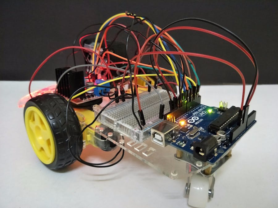
8 Place All the Components on the Robot Kit
You can place your components on the robot kit so that it looks neat and nice.
Below is my kind of assembly :
10 Replace code
From circuito.io, you should download the Firmware code and replace its loop and define with the code below.
After that, you have to download the library for DC motor. You can refer here .
11 Upload Code
Connect with USB cable to upload your code to arduino and run the robot !
12 Complete
Congratulations ! You have completed you project. Try to let the robot kit move within black lines.

Comments