


Hardware components | ||||||
_ztBMuBhMHo.jpg?auto=compress%2Cformat&w=48&h=48&fit=fill&bg=ffffff) |
| × | 1 | |||
 |
| × | 1 | |||
| × | 1 | ||||
| × | 1 | ||||
| × | 1 | ||||
 |
| × | 3 | |||
 |
| × | 1 | |||
Software apps and online services | ||||||
| ||||||
Hand tools and fabrication machines | ||||||
 |
| |||||
| ||||||
| ||||||
 |
| |||||
An upcoming "Ugly Christmas Sweater" party was the perfect opportunity to build my first real Arduino project using NeoPixels, the RGB LED strips from Adafruit. I learned a lot on this simple project that I thought might help other beginners.
- The Arduino sketch code is broken up into multiple files and is object-oriented to make it easier to understand and extend. I used sketch tabs, .cpp, and .h files.
- I used the FastLED library instead of the Adafruit NeoPixel library for more variety in light patterns and better control over the color palette. It also supports other kinds of LED strips, so experience with this will help with other lighting projects in the future.
- I used a coding pattern that supports multitasking the Arduino, and combining multiple light patterns with each other.
- I moved the project from breadboard to "ProtoShield" and learned about using protoboards and perfboards to permanently connect components.
Note: Also, I made several decisions that I later regretted and I've put those in italics. Avoid my mistakes and make your own.
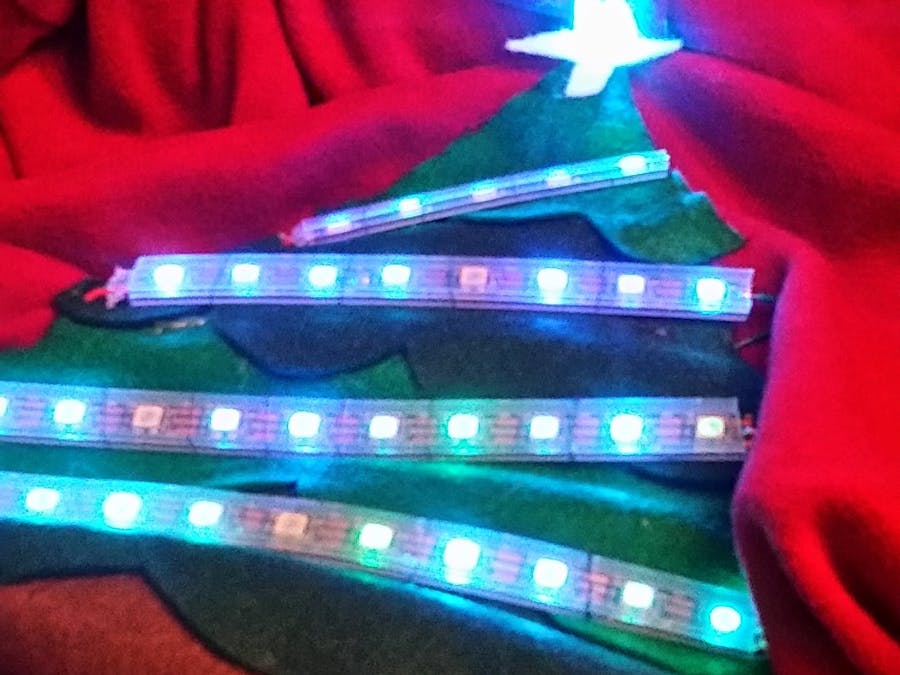
The NeoPixel LEDsI started with a basic plan to make a Christmas tree from felt and add strings of RGB LEDs. The tree would be 12" tall and 9" wide. That left room for four rows of LED decorations on the tree: 5px on the top row, then 8px, 10px, and 12px on the bottom row. I cut the tree out of felt and hot glued it together.
The NeoPixels arrived in a long reel. I connected the NeoPixel strand to a simple circuit on my breadboard, a separate power supply, and Arduino then ran the sample light patterns to make sure everything worked. These draw quite a bit of current, so if you're going to test with the whole reel you probably need a separate power supply so you don't harm your Arduino.
Adafruit has a superb guide for getting started, the NeoPixel Überguide. The simple circuit was basically four connections:
- Connect 5V on the strip to 5V on a 5V 2A external power supply
- Connect GND on the strip to GND on the power supply
- Connect a 1000µ capacitor between 5V and GND to prevent a surge
- Connect D(in) on the strip to a 470kΩ resistor and then to D5 on the Arduino
I ran some of the default light patterns with the Adafruit library and then the FastLED library to make sure everything was working before the next step. I'm a big believer in testing at each step.
The FastLED LED Animation LibraryI really liked using the FastLED library. First of all, you can specify colors as hue, saturation, and value (brightness), or HSV. The hue is the angle around the color wheel, from 0 to 255. It's easy to make the NeoPixels shift through the rainbow.
for(byte hue = 0; hue < 255; hue++) {
  for(int i=0; i < NUM_LEDS; i++) {
    leds[i] = CHSV(hue, 200, 255);
    FastLED.show();
  }
  delay(25);
}
In addition, FastLED has adjusted the color palette so that yellow gets equal billing. There's a good explanation of color spaces on their wiki.
And finally, the demo patterns that came with it are easy to call and were a lot of fun. Here's an example of how you can mix patterns together.
void rainbow()
{
 // FastLED's built-in rainbow generator
 fill_rainbow(leds, NUM_LEDS, gHue, 7);
}
void rainbowWithGlitter()
{
 // built-in FastLED rainbow, plus some random sparkly glitter
 rainbow();
 addGlitter(80);
}
void addGlitter( fract8 chanceOfGlitter)
{
 if( random8() < chanceOfGlitter) {
   leds[ random16(NUM_LEDS) ] += CRGB::White;
 }
}
Next, I cut the NeoPixel strips to fit the tree. They're easy to cut and correct spots to cut are clearly marked.
I decided to tie all of the 5V (red) and GND (black) lines together on the left side and connect those to an SMT plug. This shortened the distance from the power supply to any particular pixel. It also meant I had fewer wires cluttering up the right side of the tree. Then I connected the data line (green) from the right side of the bottom row to the left side of the next row up, and so forth.
Note: This method worked, but I wouldn't use it again. With such short strips, distance to the power supply wasn't a factor. And though there were fewer wires cluttering up the right side of the tree, I wound up with a mess of wires on the left side.
After all the soldering, I connected them to the Arduino for another test.
In the picture below you can see a black 3-wire cable with an SMT connector in the middle that goes to my breadboard. LED 1 was at the bottom left, LED 13 was the first pixel in the second row, and so on. Success!
Note: This is where the sweater got ugly. Tying together four power wires, four ground wires, 1 data wire, and 3 wires from the jack resulted in an ugly wad of wires soldered together. If you have better ideas, I'd appreciate your comments.
Also, now that there were only 35 LEDs instead of an entire 2 meter reel, I was able to use the Arduino to power them a stop using the 5V power supply. I also decided to power the LED strips with 3V instead of 5V. They were too bright against the background of the felt tree, so cutting down the power was fine. I've shown this on the breadboard illustration in the next section. The good news was that a 5V USB cell phone charging battery was enough for the Arduino and the lights. Now it was officially wearable.
The RGB LED StarAfter this, I added the RGB LED (not a NeoPixel) for the star. It required PWM control for red, green, and blue, plus the anode to be connected to power on the Arduino. That's four wires more.
I connected each of the pins for red, green and blue to 220Ω resistors and then to D4, D3, and D2 on the Arduino. This is roughly the breadboard. Note that now everything could be powered by a USB source into the Arduino. I used a cell phone charging battery.
I didn't have a plug on-hand that I would wire this into, so I wound up soldering these lines directly to the Arduino ProtoShield. Now the sweater had a three wires from the NeoPixels and four wires from the RGB LED. Seven wires is a lot of clutter.
I wrote a simple object to change the color of the star each time the pattern on the tree lights changed. It's a little more code than if you just added a function to the main body, but for two good reasons:
- I wrote the color change pattern as an object so that it could have local variables that kept track of its state, and advance the color correctly. The fewer global variables, the better.
- I put it into a separate file so it was easier to isolate changes to it, and thus easier to debug or extend. (Also, no long, long scrolling required to find the section I want to work on.) This required making a ".h" file to declare the public and private variables and functions, and a ".ino" file with the actual code.
- I have a half-dozen ideas for color patterns and transitions, and though I didn't get them implemented in time this year, I wanted the code to be a good foundation for the patterns to come.
There's a really excellent tutorial that explains how to write Arduino code that multitasks, uses objects, and avoids the delay() function, and I modeled my code after that. Check out Multitasking the Arduino part 1 by Bill Earl.
Here's LedWheel.h.
// LedWheel.h
#ifndef LEDWHEEL_H
#define LEDWHEEL_H
class LedWheel
{
   // Rotates led through color wheel
   // Changes to next color each time called
   private:
   // Params, initialized at startup
     int redPin;
     int greenPin;
     int bluePin;
   // State variables
     int currentColor; // 0 to 5
   public:
     LedWheel(int setRedPin, int setGreenPin, int setBluePin, int setColor);
     void Update();
};
#endif
And here's LedWheel.ino.
// LedWheel.ino
#include "LedWheel.h"
LedWheel::LedWheel(int setRedPin, int setGreenPin, int setBluePin, int setColor) {
 // Constructor; inits vars and state
   redPin = setRedPin;
   greenPin = setGreenPin;
   bluePin = setBluePin;
   pinMode(redPin, OUTPUT);
   pinMode(greenPin, OUTPUT);
   pinMode(bluePin, OUTPUT);
   currentColor = setColor;
 }
 void LedWheel::Update() {
   // Call periodically to change color
   currentColor = (currentColor + 1) % 6;
   switch (currentColor) {
     case 0: setLedColor(128, 0, 0); break; // red
     case 1: setLedColor(128, 128, 0); break; // yellow
     case 2: setLedColor(0,128,0); break;  // green
     case 3: setLedColor(0,128,128); break; // aqua
     case 4: setLedColor(0,0,128); break;  // blue
     case 5: setLedColor(128,0,128); break; // purple
   }
 }
Note: I realized later that I didn't do a good job of isolating this code. My next project, LED Cloud, follows this pattern but is a much better implementation. It also has four color transition patterns (instead of one).
This transition pattern is pretty simple -- no fade-in, no intermediate colors, no twinkles. I've since developed more patterns and I'll be updating this project and LED Cloud on in Github.
In the main code, I included and called it with this. The EVERY_N_SECONDS() function is part of FastLED and is pretty handy. The loop runs as quickly as it can, updating the NeoPixel strip, and my star.Update() is called only when I want things to change. No delay() function is used.
// Near top of file
#include "LedWheel.h"
LedWheel star (4, 3, 2, 0); // create object called star, init pins and state
// other stuff omitted
void setup() {
  // code to initialize other stuff omitted
  star.Update(); // Set star colors according to state 0 (red)
}
void loop () {
  EVERY_N_SECONDS( 10 ) {
    // code to run other stuff omitted
    star.Update();
  }
}
Now that everything worked on the breadboard, I transferred it to an Adafruit ProtoShield. This was much easier than using perfboard because it matches the Arduino size, has headers that plug into the Arduino, the pins are labeled, and it has handy places to solder components. You can see in the picture there are strips with GND and 5V, for example. It's easy to see how I soldered pins 2, 3, 4 to the resistors for the RGB LED, and pin 5 to the resistor for the NeoPixel strip.
At the time I didn't know I could make connections on a perfboard by making little solder bridges under the board. The ProtoShield solved this problem for me by having little solder pads that spanned three holes. You can see how I used one to connect 3V on the Arduino (red wire) to the power wire for the RGB LED and the power wire for the NeoPixel strip.
I didn't move the capacitor to the ProtoShield. That was an oversight. It's there to prevent surges from the external power supply from damaging the NeoPixels. I haven't had an problems with this, which could mean I'm lucky, or it could be that you don't get that kind of surge from the Arduino.
Note: If I were doing this again and had the parts on hand, I'd solder a 7-pin connector to the ProtoShield, put the 7 wires from the sweater into a connector, and be able to plug and unplug the sweater from the board.
I really enjoyed this as a starter project because the work to fun and work to knowledge gain ratios were pretty good. The results were immediately blinky and ugly, thanks to the default libraries, and I learned a lot of key things about development that will make the next project faster, and make it easier to build larger-scale projects.
- Calculating (or estimating) power requirements
- Using Fritzing for the breadboard and schematics
- Transferring from a breadboard to a protoboard
- Considerations about connectors, power requirements, and form factors
- Good (better) coding practices
The Arduino has a pretty large form factor, obviously, and this project only needed 4 PWM pins. If I used a single NeoPixel for the star, it would have needed only 1 PWM pin.
I could also use individual RGB pixels with conductive thread, or a premade string of pixels. Either of these would help me make a sweater that just shows the pixels and not the plastic strip that my sweater currently has, but both options cost more.
I think I could have run this from an Adafruit Gemma or a Adafruit Trinket. I tried to make them work, but problems with my USB hub and cables arose and I ran out of time.
I simply ran out of time to extend the light patterns, so keep an eye on this in Github to see developments.
Last but not least, I'd like to experiment with IR signalling between sweaters. If your eyes light up when you see a friend, shouldn't your sweater light up too?
Useful links: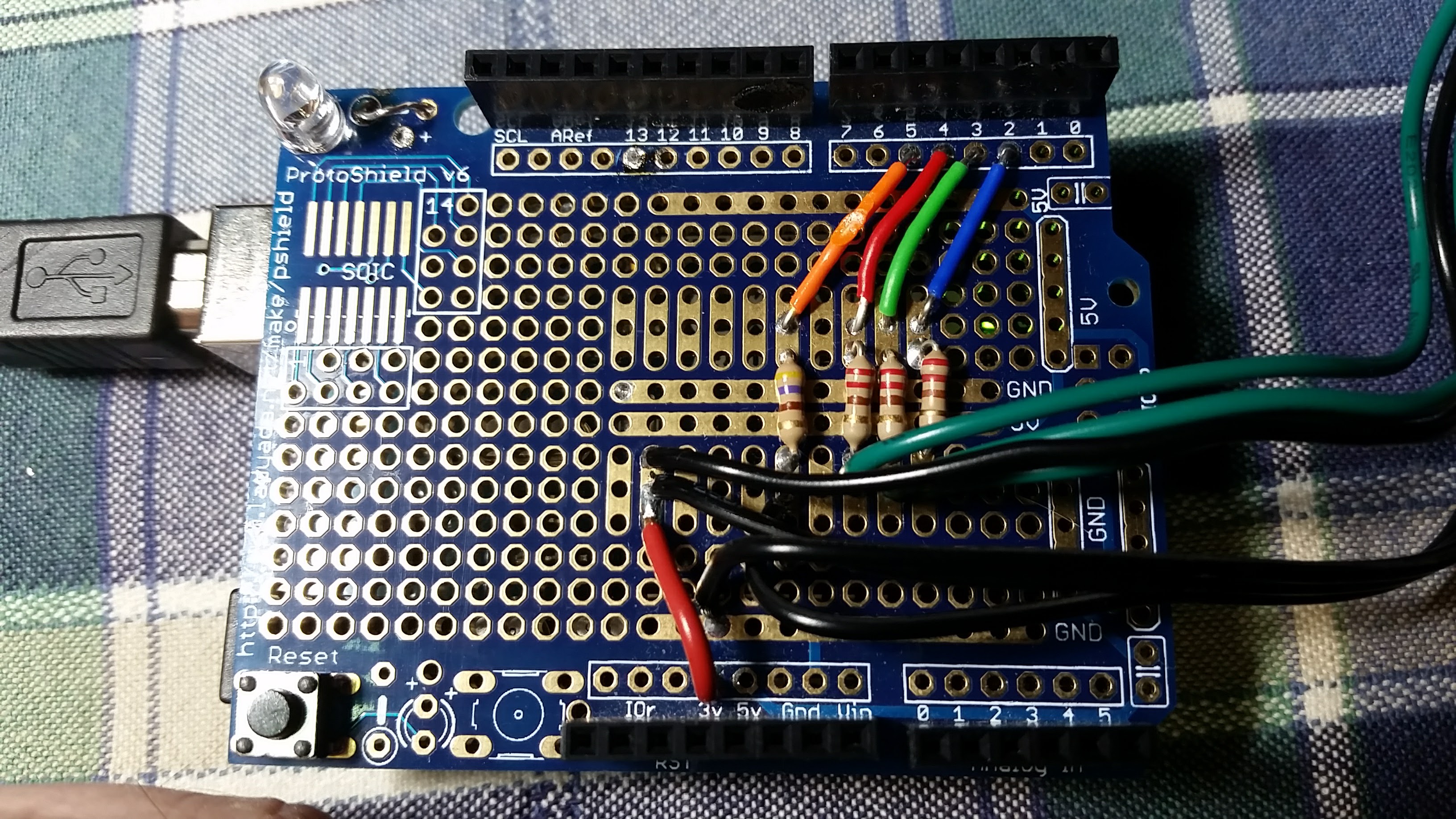


Comments