Soldering iron and the other items in a soldering set including lead, fume extractor, safety goggles, etc.
Story
Lo-fi Prototyping (continued)
With last week's lesson in mind of creating communicative and more purposeful prototypes, I started off the second week by doing just that. I created a better prototype with callouts using tape that was about the size of the parts needed.
This prototype gave me a very clear picture of how my final car would almost look like.
1 / 4 • Caster mock-up
Electronics: Getting the motors to work
My next step was to get the wheels and DC motors working before re-iterating on the chassis. I chose to do this because I didn't know how the electronics would turn out compared to the chassis. This ended up being the correct decision because ended up adding more elements to my chassis such as the L298 H-bridge controller (for controlling the DC motors), 6V battery pack (for powering the L298), and 9V battery pack (for powering the Arduino Uno). I adjusted my final chassis later accordingly.
All the electronics components
I ran into a lot of difficulty here, trying to find a good online tutorial to make DC motors run. I pieced together parts of different tutorials to get them working. The tutorials I used will be included at the bottom of this post. The premise of the wiring is that you have the INs and OUTs on the L298. These correspond to inputs controlled by your Arduino and outputs, which are the motors. You wire a first motor to OUT1/2 and the second to OUT3/4. You wire IN1/2/3/4 to your Arduino.
Circuit diagram is included at the end.
Electronics: Setting up the remote control
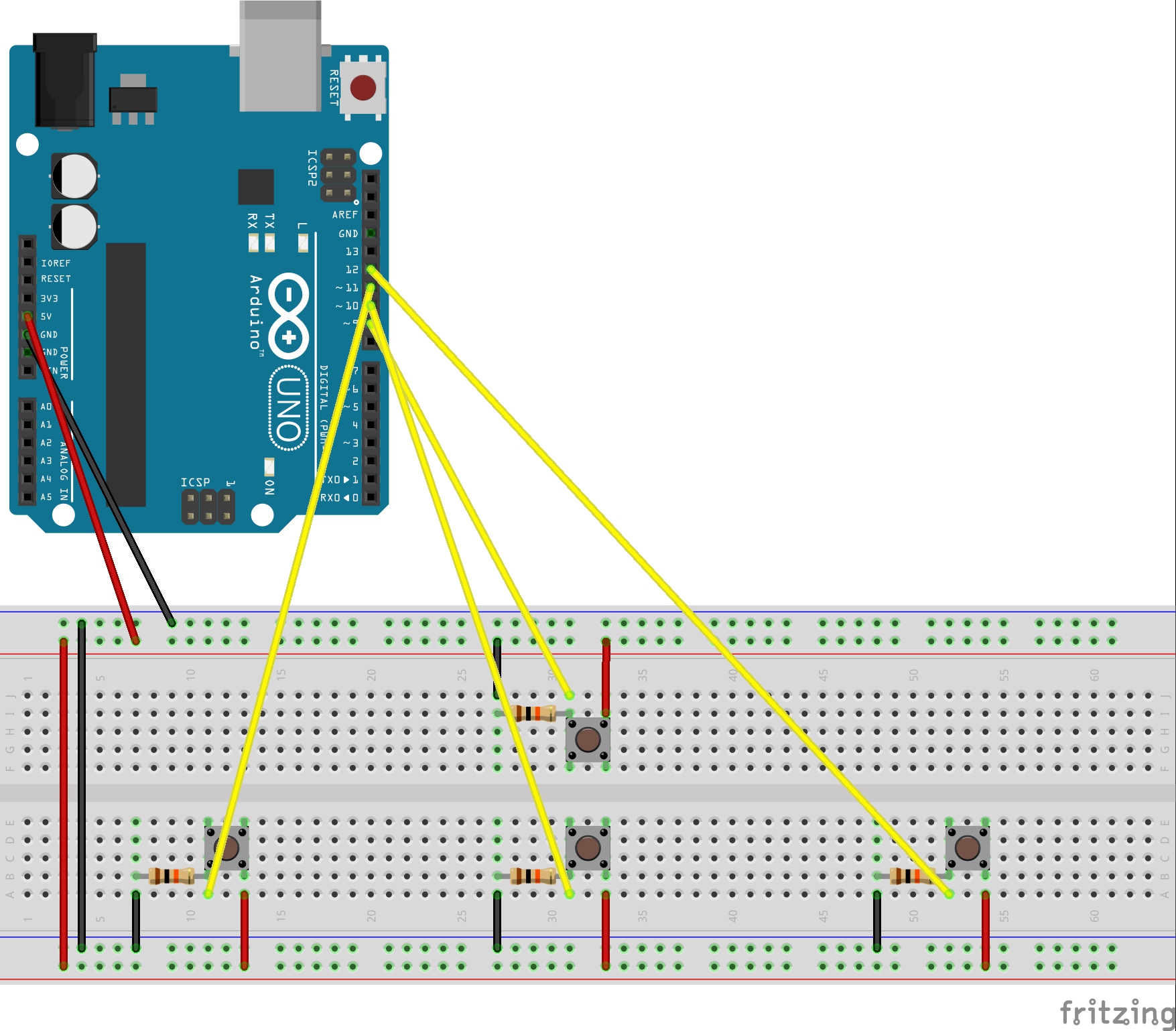
I added push buttons connected to other pins and a solderless breadboard in order to control the motors. The remote control interface is designed to mimic the WASD gaming controls on keyboards.
WASD control with pushbuttons
The remote control was hard to use because of all the jumper cables, so I cut solid core wires at just the right lengths for the breadboard in order to reduce clutter.
The Arduino code for running the motors with the switches is included below. The way DC motors work with the code is that each motor has two ends. You digitally send to these motors' inputs either a HIGH or LOW signal. Let's take for example a motor whose outputs are OUT1 and OUT2 and inputs are IN1 and IN2. Sending a HIGH to IN1 and LOW to IN2 will make the motor spin in one direction. Sending LOW to IN1 and HIGH to IN2 instead will make it spin the other way. This could be "forward" or "backward" depending on your wiring. Sending LOW to both or HIGH to both will not make the motor spin.
More Lo-fi Prototyping and Chassis Testing
With my electronics ready to go, I re-worked my chassis to include the new components.
More cardboard prototyping
I also needed to figure out a way to hold all the components in place when the car is moving. I played around with 3 different holding mechanisms using cardboard shown below.
1 / 4
I went through the pros and cons of each possible solution and ended up deciding to use a dual layer chassis that allows for embedding components after analyzing tradeoffs.
I created one more cardboard prototype that would eventually become my final chassis. Again, I included callouts and accurate measurements of the components. Doing so made creating the .AI files for laser cutting much easier and saved me lots of time and probable heartache.
Refined cardboard prototype
Laser cut chassis
For my caster, I 3D printed one I found on thingiverse and used a marble as the caster wheel. It works really well!
Caster on the left side, double-sided tape between layers
Working Design
I laser cut the chassis using two pieces of black acrylic with a matte finish on one side. One layer was just the chassis while the second layer cut was the chassis with cutouts that are the sizes of the components. I placed the layer with the cutouts on top of the other in order to create the embedding for the electronics. I used double-sided tape to stick the two together and also used double-sided tape to hold down the motors.
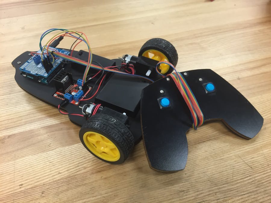
I don't have a picture or recording of the working car that uses the solderless breadboard as the remote control, but it did work. Below is a picture of what came the following week when I actually switched out the breadboard and built a game controller remote.
Working design
Problems
Problems I ran into included motors not working, 1 motor not working, motors working but one won't spin reverse for some reason, etc. Most, if not all, of these problems stemmed from poor wiring. I didn't solder anything on and instead used electrical tape, which caused some wires to loosen without me even noticing. Sometimes I didn't fully screw down the screw on the L298 h-bridge, which lead to loose connections too. Sometimes, I even forgot to turn the battery pack on.
Lessons
Don't be afraid to ask other people for help and help other people out too. I got a lot of help and thoughtful opinions from my classmates and Chris while working in the lab. Seeing what other people were doing and listening to their thought processes on their cars helped me to evolve my own design and add cool elements I wouldn't have thought of.
Sketch to test if motor works. If it doesn't, check your wiring.
// Single motor sketch for testing// Matthew Chiang Des Inv 90-2// motor 1intIN1=7;// Set IN1 to digital pin 7. Your wire should literally go from 7 on the Arduino to IN1 on the L298intIN2=6;voidsetup(){pinMode(IN1,OUTPUT);// Set the pin IN1 and IN2 to behave as an outputpinMode(IN2,OUTPUT);}voidloop(){// For clock-wise motion, IN1 = HIGH, IN2 = LOW// Test one motordigitalWrite(IN1,HIGH);digitalWrite(IN2,LOW);}
rc-controls-breadboard.ino
Java
For WASD controls
// Which L298 IN is hooked up to which digital pin on the Arduino?// If you change these, make sure one IN for each motor is linked to a PWM digital pin.// Motor 1intIN1=7;// IN1 on the L298 is linked to digital pin 7intIN2=6;// pwm// Motor 2intIN3=4;intIN4=3;// pwm// The buttons are hooked up to which digital pins?constintupButtonPin=9;// the number of the pushbutton pinconstintdownButtonPin=10;constintleftButtonPin=11;constintrightButtonPin=12;// WHAT, MAKING THIS 0 MADE IT GO FOREVER// Variables will change:intupButtonState=0;// variable for reading the pushbutton status; 1 on (pressed) 0 off (unpressed)intdownButtonState=0;intleftButtonState=0;intrightButtonState=0;voidforward(){digitalWrite(IN1,HIGH);digitalWrite(IN2,LOW);digitalWrite(IN3,HIGH);digitalWrite(IN4,LOW);// analogWrite(IN3, 255);// analogWrite(IN1, 255); // IN3 is attached to digital pin 3 which is a PWM pin. }voidbackward(){digitalWrite(IN1,LOW);digitalWrite(IN2,HIGH);digitalWrite(IN3,LOW);digitalWrite(IN4,HIGH);}voidturnLeft(){// Turn left by stopping/slowing the left wheel and moving the right wheel forwarddigitalWrite(IN1,LOW);// LOW for stoppingdigitalWrite(IN2,LOW);digitalWrite(IN3,HIGH);digitalWrite(IN4,LOW);// analogWrite(IN3, 255); // uncomment for slowing// analogWrite(IN1, 100);}voidturnRight(){// Turn right by stopping/slowing the right wheel and moving the left wheel forwarddigitalWrite(IN1,HIGH);digitalWrite(IN2,LOW);digitalWrite(IN3,LOW);// LOWdigitalWrite(IN4,LOW);// analogWrite(IN3, 100);// analogWrite(IN1, 255);}voidsetup(){pinMode(IN1,OUTPUT);// Set the pin IN# to behave as an outputpinMode(IN2,OUTPUT);pinMode(IN3,OUTPUT);pinMode(IN4,OUTPUT);// Set up the buttonpinMode(upButtonPin,INPUT);pinMode(downButtonPin,INPUT);pinMode(leftButtonPin,INPUT);pinMode(rightButtonPin,INPUT);}voidloop(){// read the state of the pushbutton valueupButtonState=digitalRead(upButtonPin);downButtonState=digitalRead(downButtonPin);leftButtonState=digitalRead(leftButtonPin);rightButtonState=digitalRead(rightButtonPin);// For clock-wise motion, IN1/3 = HIGH, IN2/4 = LOW. This could be different depending on your wiring.// Move both wheels forward if upButton is pressed.if(upButtonState==HIGH){forward();}elseif(downButtonState==HIGH){backward();}elseif(leftButtonState==HIGH){turnLeft();}elseif(rightButtonState==HIGH){turnRight();}else{// Stop all wheels if unpresseddigitalWrite(IN1,LOW);digitalWrite(IN2,LOW);digitalWrite(IN3,LOW);digitalWrite(IN4,LOW);}}


_ztBMuBhMHo.jpg?auto=compress%2Cformat&w=48&h=48&fit=fill&bg=ffffff)


Comments