Arduino "Don't Hit the Number" number guessing game with Keypad and LCDBy Mak Wai Kin
This project was inspired by Arduino Keyless Door Lock System with Keypad and LCD by Ali Hamza. We are required to choose a project and modify it for our class assignment. In this project, we are going to make a number guessing which uses a 4X4 keypad to enter the keys and a DC lock to trigger and push the object away when the player hit the matching number. A 16X4 LCD will be used for display.
Required ComponentsThe components required for this project are as follows
How Does it Work?The initial number stored in the EEPROM is '1234'. When connected to the power source, the LCD will display '#' for organizer to set a new number for the game. For example, the organizer set the new number as '1111'. If the player key in number other than '1111', the LCD will display 'Wrong Guess' and let player to key in number again. If the player key in the matching number which is '1111', the LCD will display 'BOOOOM!!!' and trigger the DC lock to push away the object.
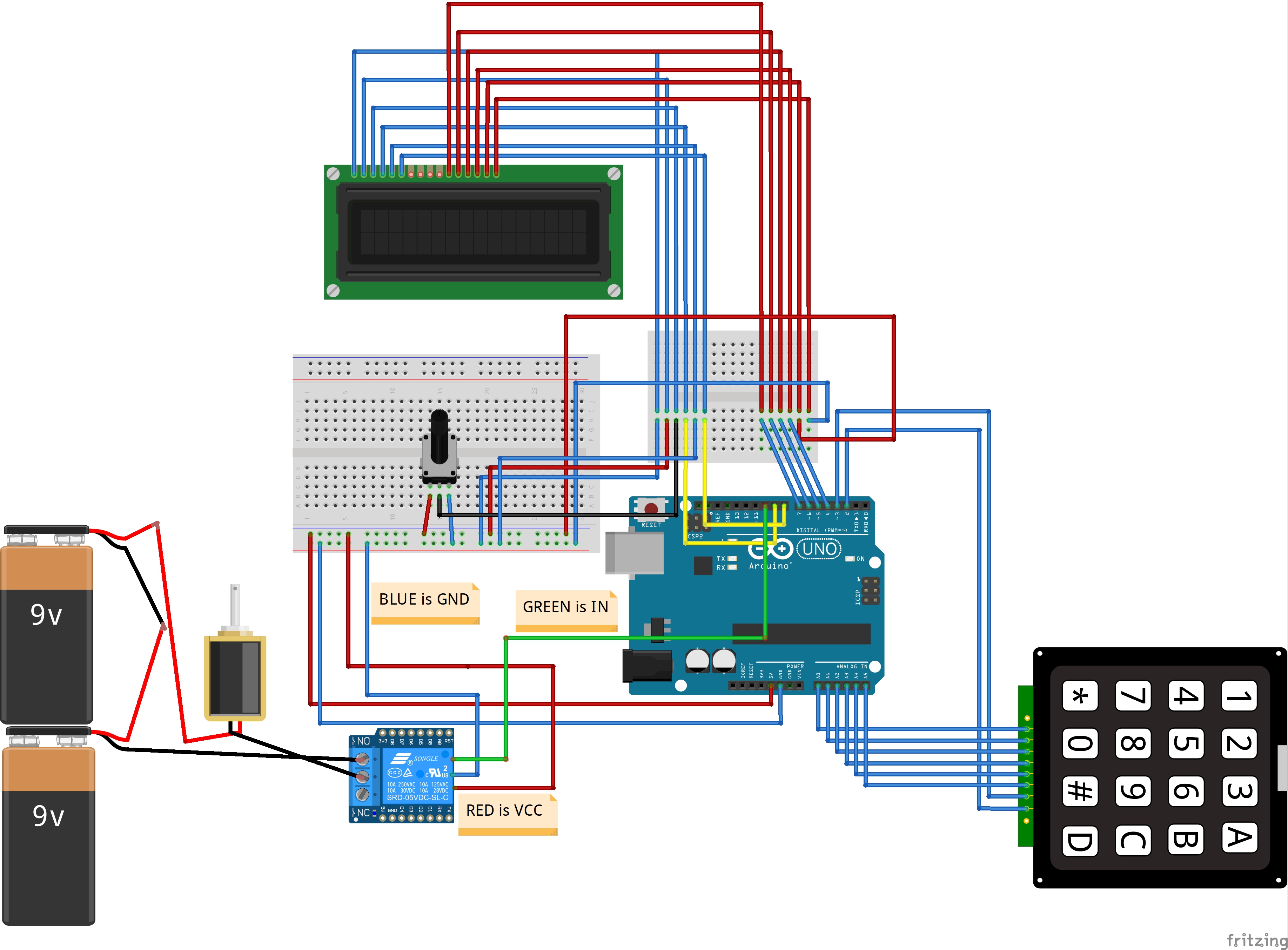
Circuit ConnectionsWe have to connect the 4X4 keypad to the Arduino so that we can key in number. First, we connect the first six pins on the 4X4 keypad to the A0 and A5 pins on the Arduino. Then connect the last two pins on the 4X4 keypad module to digital pins 3 and 2 on the Arduino.
After that, connect the LCD to the Arduino for display. The connections for LCD to the Arduino are as follows.
- Connect pin 1 on the LCD, which is the VSS pin, to GND on the Arduino
- Connect pin 2, which is the VDD pin, to the 5V pin on the Arduino
- Connect pin 3, which is the V0, to the middle of the 10k potentiometer and connect the other two pins on the potentiometer to 5V and GND on the Arduino. This pin is for setting the LCD’s contrast.
- Connect pin 4, which is the RS pin, to pin 9 on the Arduino
- Connect pin 5, which is the R/W pin, to the GND pin on the Arduino
- Connect pin 6, which is the Enable pin, to pin 8 on the Arduino
- Connect pins 11, 12, 13, and 14 which are the data pins, to the pins 7, 6, 5, and 4 on the Arduino
- Connect pin 15, which is the LCD’s backlight pin, to 5V on the Arduino
- Connect pin 16 on the Arduino, which is the negative pin of the backlight, to GND on the Arduino
Lastly, we will connect the DC lock with the Arduino. The Lock operates on a voltage from 12 to 48V, so we cannot directly connect it to the Arduino. To connect it to the Arduino, we will require a relay and a battery.
Connect the signal pin of the relay(IN) to pin 10 on the Arduino and the lock’s VCC and GND to 5V and GND on the Arduino. Then on the other end of the relay, connect the negative of the battery to the common on the relay and the NO (Normally open) on the relay to one side of the lock. Then connect the other side of the lock to the positive terminal on the battery.
Video 


_nBZuIOBB3k.jpg?auto=compress%2Cformat&w=900&h=675&fit=min)
_ztBMuBhMHo.jpg?auto=compress%2Cformat&w=48&h=48&fit=fill&bg=ffffff)


Comments