


Hardware components | ||||||
 |
| × | 1 | |||
| × | 1 | ||||
| × | 1 | ||||
Software apps and online services | ||||||
 |
| |||||
 |
| |||||
 |
| |||||
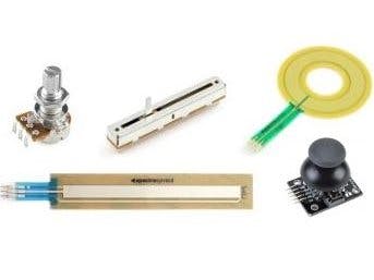
All the transducers that behave like a potentiometer can be connected to the pins of the Theremino system and read immediately. For the “Pintype”, you can choose Adc8 or Adc16 (Adc16 = greater accuracy).
Here you will find samples (with great prices) of various types of sensors and classic knobs that behave like potentiometers:
- www.sparkfun.com Membrane Potentiometers
- www.sparkfun.com Flex Sensors
Even linear transducers can be connected directly. (Check potentiometers from 1 k to 100 k; if in doubt, send the DataSheet before buying.)
Analog JoysticksThere are many perfect analog joysticks to the system Theremino.
The model in this picture is easy to connect and also has a push button. It can be easily found on eBay for less than 5 Euro (search: Analogue Joystick Controller).
There are also much smaller analog joysticks (for the playstation) or very large (with four side potentiometers). Please note that it may be difficult to mount them mechanically and connect the wires to the potentiometers. Always check that they are analog.
Powering a PotentiometerPotentiometers and transducers must be powered with voltage 3.3 volts. This to not send voltage over 3.3 volts to the input pins and to get the right range from zero to maximum reading them with the pins configured as Adc16.
To get the 3.3 volts, you may count a resistor between + 5V and potentiometer, calculated on the basis of the resistance value of the potentiometer to obtain 3.3 volts. This method, however, would have two flaws: the first is that the 5 volts derived from USB port is quite loud and can also vary by half a volt from one computer to another. The second flaw is that the actual resistance value of the potentiometer is often quite different from the theoretical. The actual voltage will not be 3.3 volts exactly, and you won't succeed in arriving at it most times or it will come before the end of the stroke. To avoid these problems, it would be better that the voltage drop to power the potentiometer 3.3 volts; see, for example, the one shown at the end of this document.
To power the potentiometers, you should connect the two ends of the potentiometer to the 3.3 volt socket and GND ICSP-AUX pins, and connect the Central Server to input PIN connection SIG, as shown in the following pictures:
This image refers to the connection of the “ribbons” (used in the ThereminCello) but the principle is valid for all sensors acting as a potentiometer.
This image refers to the connection of linear transducers, but the principle is valid for all sensors acting as a potentiometer.
CAUTION: Make sure that the potentiometer's Central (2) is connected to pole “SIG”, one of the Theremino PIN. If you connect the potentiometer Central to “GND” or to “3.3V”, the potentiometer can overheat and be ruined!!!
Instead the two extremes of the potentiometer (1) and (3) that bring the power (+3.3V and GND) can be switched between themselves without damage. Swapping (1) with (3) can serve to reverse the measures relative to the direction of motion.
Many potentiometers can be connected in parallel to the poles 3.3 and GND. But each potentiometer must have its central strand (2) separate and attached to a separate “SIG” pole.
The inner resistance of the potentiometer is not critical. All manufacturers of linear transducers use values from 1 k to 100 k, so it should all go well. (Even less than 1 k and above 100 k might work, but in the first case it would consume too much current and the latter would have little linearity and increased noise picked up by the wire.)
A potentiometer might also be used as a variable resistor if you're using it with only two terminals (freeing one of the extremes). This type of connection acts as simply simplicity - only two wires and no power. As a disadvantage though, to use exactly the whole range of values (normally from 0 to 1000), you should use a potentiometer from 50 Kohm precisely where you normally will use a potentiometer from 47 Kohm that produces values between 0 and 940, with some wiggle room; and finally, you will have to fix the software.
Please download the complete documentation and source code from here.
For a complete view of the Theremino System, please visit here.


Comments