


Hardware components | ||||||
| × | 1 | ||||
 |
| × | 1 | |||
 |
| × | 1 | |||
 |
| × | 1 | |||
| × | 1 | ||||
Software apps and online services | ||||||
 |
| |||||
Hand tools and fabrication machines | ||||||
 |
| |||||
This project was part of the Lane Tech HS Physical Computing Lab course. I created this project as part of the Home Automation / IoT project.
Kettle Warranty Disclaimer:According to the Care and Use Guide that ships with the kettle "This warranty does not cover glass, filters, wear from normal use, use not in conformity with the printed directions, or damage to the product resulting from accident, alteration, abuse, or misuse." Do not attempt this project without accepting that the kettle's warranty will be voided.
The GoalLiving in a home that is far from tech savvy brings about some objections to hacking appliances. With that in mind - the goal of this project was to add internet functionality to an electric kettle while minimizing change to the physical function of the kettle.
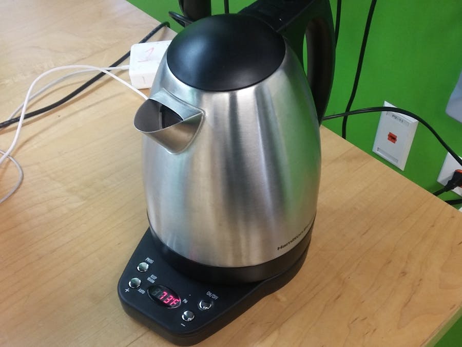
The KettleThe kettle I used for this project just happened to be one that I had. Luckily it turned out to be a great fit for the project. The plastic base of the kettle leaves plenty of room for installing electronics and all of the functions are controlled digitally.
Another Hackster user, Waldemar Sakalus, did a bit of research and decided on a similar kettle - so it seems likely I did not end up with a bad starting model. He hacked his to toggle and read the powerstate using an optocoupler and Photon. If you are interested in another method, or checking the powerstate, check out his project.
DisassemblyThe base of the kettle is secured by 5 screws on the bottom side. Two of these screws require a 3.5mm phillips screwdriver but the other three require a 2.5mm tri-wing. I recommend obtaining a tri-wing screwdriver but the screws can be forced using a flathead at the risk of stripping.
Open SesameOnce the screws are removed the base should split into two halves. Unplug the 5-pin connector to separate them entirely. The bottom half will be used for storing the relay, breadboard, and photon. The top half holds the circuit board you will need to solder to.
SolderingThis project only requires soldering two joints. I used two pieces of solid core wire that were about long enough to reach across the kettle. On the top half, look for the top left button (oriented with the buttons facing down). Solder a wire each to opposite sides of the button.
The RelayI used a 5VDC-120VAC relay because it was what I had around - a much lower output could be used. On the output side of the relay, connect one of the button wires to normally open (NO) and one to common (COM) - the order doesn't matter. On the input side connect one wire to each of the pins - I used jumpers to make the relay easily salvageable. Then simply attach the relay to the bottom half using something non conductive - I used some mounting putty.
Let There Be Light... ParticlesSnap your Photon into a small breadboard and attach it to the bottom half. Make sure to keep it towards the front and a bit angled to make attaching the usb cable easier. I used a 170 point breadboard with an adhesive backing. Connect the wires from the input of the relay: IN to any digital pin (alterable in the code), GND to GND, and VCC to VIN.
Powering the PhotonThread a USB to Micro-USB cable through the same hole as the power cord. You may have to remove a bit of plastic to get it through. Plug in the Photon.
IFTTT ConnectionFirst, connect the Particle service to your IFTTT account. Make sure your Photon is plugged in and flashed with the correct firmware. Create a new applet with whatever "if" condition you desire - IE a button or Alexa. For the the "that" operation select Particle's "Call a function" app and look for the name of your function in the dropdown. Use Particle's "New event published" applet and the notifications operation for notifications on your phone or the Google sheets add row operation for data tracking.


Comments