

Hardware components | ||||||
 |
| × | 1 | |||
| × | 14 | ||||
| × | 1 | ||||
| × | 2 | ||||
| × | 1 | ||||
Since I got my Spark Core, I’ve been fiddling without really knowing what I wanted to do with it. Lately, I’ve also been playing with my Rapiro again, and that’s when I got the idea to build a physical controller for the robot, with at its heart a Spark Core.
The controller would be used to send different MQTT messages depending on which button was pressed. Rapiro (or any other IoT device, really) would be configured with a MQTT client and would be able trigger certain actions based on the received messages.
This post is about building the controller and performing some initial tests.
Prototype
Yesterday evening, I started browsing my different bins of parts to find the necessary components to build the controller I had in mind. The list of required components was the following:
- Spark Core
- prototyping board
- pushbuttons (14)
- 1×12 female header (2)
- 4xAA battery pack
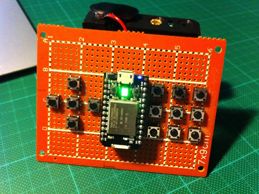
Having found everything I needed, I proceeded by laying out the different components on the prototyping board. Luckily enough, everything fit and I moved on to soldering all the buttons and making the connections.
The layout is pretty basic:
- centrally, the Spark Core with the RGB LED used to display status information
- on the left, five buttons which can be used for movement actions
- on the right, nine buttons which can be used for various functions
Code
For the code, I used Chris Howard‘s port of Nick O’Leary‘s PubSubClient for Arduino, combined with my sketch below. I’ve added comments in the code, so it should be clear what I’m trying to achieve, but to summarise:
- every pin is set as an input which is HIGH by default, using an internal pull-up resistor
- pressing a button will pull the pin down to ground, setting it LOW
- the onboard RGB LED is used to display status information:
- red: not connected to MQTT broker
- green: connected to MQTT broker
- blue: button is being pressed
- check if connected to broker, if not: reconnect
- check if button is pressed, if yes: publish MQTT message
Demo
Here’s a short video with a brief explanation of the controller, followed by a demo:
Next Steps
I’ll probably have this circuit made properly by designing a simple PCB for it. And using my 3D printer, I should be able to make a proper enclosure and buttons for it as well.
Any suggestions for improvements are welcome!


Comments