


Hardware components | ||||||
 |
| × | 1 | |||
 |
| × | 1 | |||
 |
| × | 1 | |||
 |
| × | 1 | |||
 |
| × | 1 | |||
Software apps and online services | ||||||
| ||||||
| ||||||
| ||||||
 |
| |||||
Hand tools and fabrication machines | ||||||
 |
| |||||
 |
| |||||
 |
| |||||
Our lovely cat is always begging for more food, and since we are not used to track how much he eats.... Our cat has periods of overfeeding and then under feeding.
Therefore, we decided to monitor the amount of food our cat was eating. So we create a weight measurement IoT device that log the weight and sent the measurement every 5 minutes to the cloud. Then, because was fun, we added the measurement of the room temperature, humidity and amount of light.
How to build it:The building of the device can be divided in five different areas:
1. Building the wood structure;
2. 3D print the enclosures;
3. Create all the circuits components;
4. Write the code needed to access and logs the sensors telemetries;
5. Configure the device and the data streaming to Google Cloud.
These steps are not meant to be in a sequenced order, but they are performed with a certain degree of parallelism. But to better describe the whole project they have been separated in different conceptual areas...
1. The Wood StructureWas created using few pieces of wood glued together.
The size is around 12 cm for each side. On the attachments there is the.stl file of the 3d design.
A hole was created to allow the electric connection of the weight sensor to pass on the back side. Finally, the front side was embellished by engraving a cat image (using a laser cutter).
Once the wood structure is ready the next step, is to glue the scale to the cat bowl.
Then, attach the weight sensor to the base of the wood structure as shown in the picture below
For the project 3 enclosures have been designed, each enclosure is composed of two elements, the bottom side and the upper side.
All the.stl files are added as attachments.
1 - Raspberry Pi zero enclosure
2 - HX711 enclosure
3 - DH11 + photo resistor electric circuit enclosure.
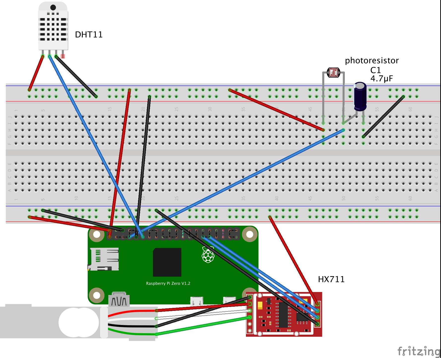
3. CircuitsThe electric implementation is straightforward and can be divided in three components:
- The measure weight (based on the 5V)
- The measure of light intensity (based on 3V)
- The raspberry zero PI connects sensors and streams, then it streams the measurements to Google Cloud.
- The load cell amplifier is a small metallic board for HX711 IC that allows to read the load cells stress and infer the weight.
The load cell amplifier cables have been soldered to the correspondent pins in the HX711 connections.
Then, the output connections and the power connections have been connected to the Raspberry Pi Zero (as shown on the circuit diagram below).
- The next element of the electric schema is the sensor DHT11 for the temperature/humidity and the photo-resistor for light sensor. They have been aggregate since they are using the same voltage 3V (the HX711 needs 5V).
Once the circuit blocks are soldered and tested, they can be connected to the Raspberry Pi Zero.
Once all the elements are connected properly and inserted in the related enclosure, we can glue them on the wood structure.
(keep in mind that it is for cats, who are attracted by loosing cables!)
All the project code is available on the GitHub repository:
https://github.com/EnzoCalogero/CatFeeder
All the Python code is supposed to run on python3.
My first suggestion is to test each sensor circuit component before going on the next steps.
For this purpose on the github repository folder "/test_hardware" for each sensor is included a Python script to verify that is working as expected.
test_weight.py --> Test the weight sensor and all its connections
dht11_example_v2.py --> Test the DH11 sensor and all its connections
photo.py --> Test the photo-resistor and all its components.
Once all the components have been tested, the next step is to run the batch script
while true
do
    	echo "Hi"
	python3.5 first.py
       sleep 5m
done
Which print out an "Hi " to let you know that the script is active and then launch the Python script first.py.
Then it repeats these steps every 5 minutes.
The Python script first.py is a modified version of the Python example on the URL:
https://github.com/ARM-software/Cloud-IoT-Core-Kit-Examples/blob/master/CPUTemp/pi_cpu_temp_mqtt.py
The script has been modified by:
- Adding 3 functions (one for each sensor ) to acquire the sensor measurements,
- Create a MQTT request for sending the measurements and related metadata to the Google cloud pub-Sub.
If you want to run the script automatically at the start-up:
- Configure the Raspberry PI to start in out-logon with CLI (not Desktop).
- append the command feeder.sh to a new line into the.bashrc file in the home folder of the user pi.
For further information regarding the library used and the installation on the Raspberry PI I would suggest the following link:
https://github.com/ARM-software/Cloud-IoT-Core-Kit-Examples
5. Configure the streaming for Google CloudThe configuration IOT Stream needs the following steps:
a. Having a valid Google Cloud Platform (GCP) subscription.
b. Create a topic and Subscriptionon GCP Pub/Sub On the Navigation menu, click Pub/Sub > Topics.
- Click Create a Topic.
- type the name to give to the home-sensors, and then click Create.
c. Create a Storage Bucket
The GCP DataFlow, needs a Google Cloud Storage bucket, for temporary store information for the process.
To create a bucket storage:
- In the GCP Console, on the Navigation menu, clickStorage > Browser.
- Click Create bucket.
- I normally use my project name as the bucket name.
- Click Create
d. Create a Device Registry
To create a device registry:
- On the Navigation menu, click IoT Core.
- Click Create a device registry.
- Specify the following, and leave the remaining settings as default:
Registry ID --> deviceReg
Region --> <closest region to you>
Default telemetry topic --> example "device-data"
Device state topic --> example "device-data"
- Click Create.
e. Create a Certificate on the Raspberry PIdevice
- Create a public/private key pair(s) for the device, with the following command.
openssl req -x509 -newkey rsa:2048 -keyout rsa_private.pem -nodes -out rsa_cert.pem
f. Create a Deviceon the Device Registry
To create a device and manually add the auth key.
- Click Devices then click Create a device.
- Specify the device and copy and paste the public certificate generated earlier
- Click Create.
g. Create a BigQuery table
The first step in streaming data to BigQuery is to create a BigQuery table.
- On the Navigation menu, click BigQuery then click Done.
- Click on your project name, then click Create Dataset.
- For Dataset ID type the dataset name example sensorHubData. Select the data location closest to you, click Create dataset.
- To add a table, click on your dataset then click Create table.
- Then add these fields on the table schema:
h. Create a Dataflow Pipeline
- On the Navigation menu, click Dataflow.
- Click Create job from template.
- Select "Pub/Sub Topic to Bigquery"
- Add all the relevant information as created in the previous steps.
- click run
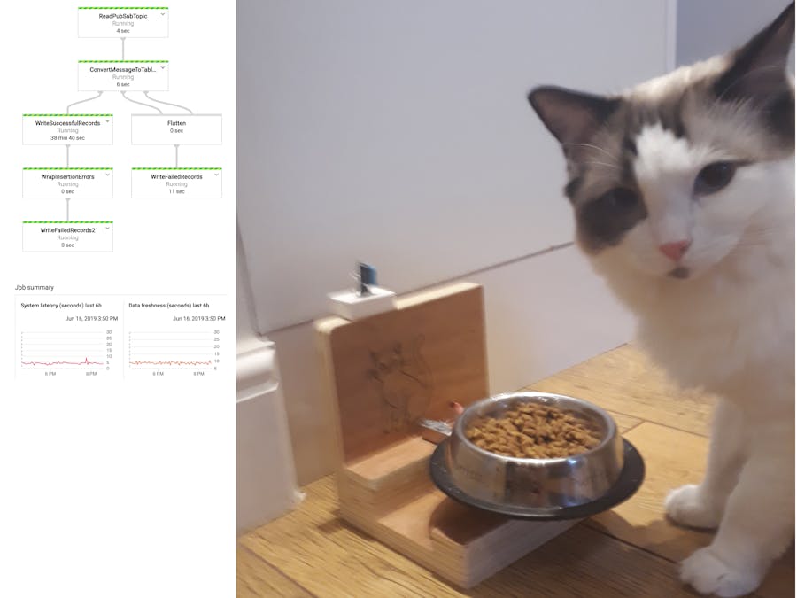
After few minutes you should have the pipeline running and start to move telemetric data from the pub/sub to the Big-query.
This chapter is a very brief overview of all the steps needed to configure in the GCP. For further information, a good source is:


_3u05Tpwasz.png?auto=compress%2Cformat&w=40&h=40&fit=fillmax&bg=fff&dpr=2)
Comments