


Hardware components | ||||||
 |
| × | 1 | |||
| × | 1 | ||||
 |
| × | 1 | |||
 |
| × | 1 | |||
Software apps and online services | ||||||
| ||||||
Creating a cloud-connected sub-1GHz RF sensor network. Revisited.
OVERVIEW
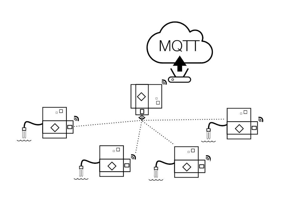
In this hackster tutorial, we will be creating a cloud-connected sensor network using the TI LaunchPad development ecosystem. We will create several sub-1GHz RF sensor nodes, which will read sensor data, print the latest readings to an LCD screen, encode the readings into JSON, then transmit the JSON-encoded payload over the sub-1GHz radio.
We will create 3 different nodes, each featuring a different sensor. In our example, we will have a water/moisture sensor, a potentiometer & an ambient light sensor. Note however, that any analog sensor could be used since we're simply leveraging an ADC pin of the microcontroller device to read the analog sensor levels. This example can be extended to support additional sensors as well if you want to collect additional datapoints!
ON-DEMAND WEBINAR!
Have a spare hour? We recorded a webinar with Element14 regarding this design! You can watch the recorded webinar here:
BUT FIRST, A FEW VIDEOS...
Before we dig in, let's take a look at a few videos to quickly demonstrate what we'll be making today!
THE SENSOR NODES
As you can see, each sensor node is reading sensor values, printing them to the LCD screen & sending them to our sub-1GHz RF/Wi-Fi gateway. Each sensor node also displays the type of sensor data it is reading on the LCD screen. In the video clips below, you see a RED LED blip several times a second. This signifies that a new sensor reading was acquired, encoded into JSON & sent over the RF radio. In addition, we are also printing the JSON-encoded payload to the PC serial monitor as well.
Each sensor node is mostly identical, each featuring the following components:
- MSP-EXP430FR6989 LaunchPad with integrated segmented LCD
- 430BOOST-CC110L Sub-1GHz RF Radio BoosterPack
- An analog sensor from Seeed Studio (Moisture, Ambient Light, Potentiometer were used in this demo)
THE GATEWAY & THE CLOUD
The cloud-connected gateway receives the data coming from the various sub-1GHz sensor nodes & forwards it up to the cloud by publishing the data over MQTT.
Once our WiFi gateway tosses the sensor data over the MQTT fence, we are able to receive that data using a cloud-hosted MQTT client who is subscribed to our WiFi gateway. Now that our data is in the cloud, the possibilities are endless! In this particular tutorial, we created a cloud-hosted node.JS application that visualizes our sensor data using gauges and sparklines.
The gateway is pretty simple & pairs the following hardware together:
- CC3200-LAUNCHXL Wi-Fi LaunchPad development kit
- 430BOOST-CC110L Sub-1GHz RF BoosterPack
LET'S BUILD THIS THING!
HARDWARE SETUP
Now that you have an idea of what we'll be building today, let's go ahead and start putting together the hardware.
The hardware for this project is pretty straight forward thanks to the modularity of the TI LaunchPad ecosystem. For the sensor nodes, we'll be pairing the MSP-EXP430FR6989 LaunchPad + 430BOOST-CC110L RF BoosterPack + Grove sensor module.
Putting together the RF sensor node:
- Plug the Grove analog sensor to one end of the Grove ribbon cable.
- Add a male-to-male jumper wire to the other end of the Grove ribbon cable. Plug one end of the jumper wire to the yellow "signal" pin of the ribbon cable.
- Plug the GND and VCC pins of the Grove ribbon cable to the GND and VCC pins on the bottom-right corner of your LaunchPad kit. This will power our analog sensor from the LaunchPad.
- Plug the other end of the male-to-male jumper wire to pin #23 of the LaunchPad (P8.4 on the MSP-EXP430FR6989 LaunchPad kit)
Now that we've made one sensor node, the setup can be repeated for additional sensors. It also very easy to change the sensor so that each node is collecting a different type of data.
Putting together the Sub-GHz RF / Wi-Fi Gateway:
Our Wi-Fi Gateway is pretty simple. We are using the CC3200-LAUNCHXL Wi-Fi LaunchPad Development kit + 430BOOST-CC110L RF BoosterPack. By plugging these 2 boards together, we create a system that is able to communicate to our RF sensor nodes & talk to the cloud over Wi-Fi.
LET'S DO SOME PROGRAMMING!
Now that our hardware is setup, let's program our boards! The code provided below was written using Energia, which is an open source rapid prototyping coding environment & API framework based on Wiring/Arduino.
You can program your boards using the Energia IDE, which can be downloaded & installed on Windows, Mac or Linux. Another option is to use CCS Cloud, which is a new online web-based IDE that enables developers to write, compile & flash code through their web browser.
***Note: we are using a LCD library for the on-board segmented LCD display. If the current version of Energia you are using doesn't have the library baked in, I provided a link to the GitHub repo in the software section below. You can add the LCD library to: My Documents > Energia > Libraries. Or, you can directly add the .h and .cpp files into your project folder.
Here's a quick breakdown of the code below:
SENSOR NODE:
SETUP
- Initialize serial port
- Initialize CC110L RF radio
- Initialize LCD display
- Print sensor type to the on-board LCD of the MSP-EXP430FR6989 LaunchPad
- Initialize GPIO pins for LEDs
LOOP
- Turn on LED to signify start of new sensor reading & attempted RF transmission
- Toggle on the "TX" icon on the segmented LCD display
- Encode the latest sensor reading into JSON format, along with other information such as sensor type & name.
- Transmit the JSON-encoded payload over the Sub-GHz RF radio
- Print the latest reading to the segmented LCD display
- Turn off the LED to signify new sensor reading & RF transmission was successful
- Turn off the TX icon on the LCD
- Delay for 250ms
NOTE: You can make a few simple modifications to this example sketch:
- Change frequency of RF transmissions. If you are doing less frequent transmissions, think about using the sleepSeconds(numSeconds) API, which puts the MSP430 microcontroller into Low Power Mode 3, which is very low power!
- Change the sensor type & sensor name
- Change the pin you connect your sensor to.
GATEWAY:
SETUP:
- Initialize LEDs. We will use 3 LEDs to provide visual notification of various activity.
- Initialize serial port.
- This example enables 2 types of provisioning to your Wi-Fi network (SmartConfig or connect to a hard-coded SSID/password). User can select the provisioning method by pressing a push button during board startup. Note that SmartConfig method requires an iOS or Android application for passing Wi-Fi credentials to the LaunchPad dynamically.
- Once connected to Wi-Fi, we print some diagnostic information to the terminal
- Then we configure and initialize the CC110L RF radio.
LOOP:
- Check to see if we're connected to an MQTT broker. If not, connect to one.
- Once connected to the MQTT broker, we check to see if there are any sub-GHz RF packets to receive.
- If RF packets are received, we turn on an LED & run the printRxData() function, which prints out the incoming RF message to the Serial Monitor, along with other diagnostic information (i.e. RSSI, etc).
- We also publish the incoming RF payload to the cloud using MQTT
- Once the payload has been forwarded up to the cloud via MQTT, we turn off the RED LED to signify that we're done publishing the latest RF packet to the cloud.
- Lastly, we call client.poll(), which refreshes a timeout to ensure we stay connected to the MQTT broker.
THE CLOUD:
Node-RED & IBM BlueMix & Freeboard.io
The cloud-side of this system was developed using Node-RED, a visual programming tool built on node.JS. Instead of running a local node.JS server, we used IBM's BlueMix Platform-as-a-Service (PaaS) to host it for us. You can sign up for a free BlueMix trial account at www.bluemix.net
They offer a single-click "Node-RED Starter" boiler plate, which will spin up a node.JS runtime & node-RED on the cloud quickly. Once this is done, you'll have your own cloud-hosted Node-RED instance running, which you can start doing cloud-side development. Once you have a Node-RED instance running, you'll be able to import the node-RED flow that is shared below. This particular flow receives the incoming MQTT messages that your Wi-Fi gateway is publishing. The node-RED flow uses the "switch" node to parse the incoming JSON messages & forwards it to freeboard.io for data visualization.


Comments