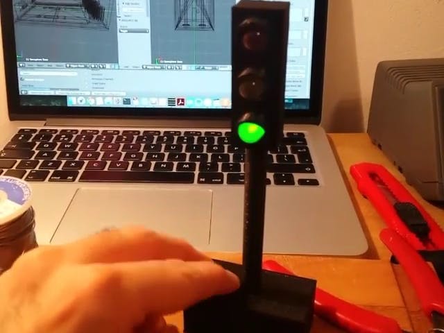
This is a small semaphore you can put on your desk. You can use it to tell whatever you want to the people around it. For example, because you need some concentration and you'd like your colleagues not to disturb you. Or to tell the status of the system you're managing. Or say which mood are you today. The possibilities are endless!
I wanted the thing to be dead-simple to use. It's not connected to Internet, it only has a button to cycle between red, yellow, green and off. But it was a nice combination of different skills I wanted to improve.
The ElectronicsThe electronics revolve around the three 10mm diffused LEDs, the ATtiny13A and a pushbutton to choose the color. I could have chosen an even simpler circuit based on some mechanical four-way switch, but because this circuit is battery-powered, I wanted the semaphore to turn off automatically after some time in case I forget it on. And this requires counting time and controlling the LEDs digitally.
To keep the size small, I decided to use two AAA batteries. They provide a voltage around 2.4V; this is enough for the ATtiny, whose minimum operating voltage is 1.8V, and the LEDs whose forward voltage is 2.1V. But when the LEDs are controlled by the microcontroller, one must take into account the maximum voltage (VOH) provided by the digital I/O port when driving a load with 20mA. By looking at the datasheet, seems like VOH is 0.7 to 1.0 volts below the operating voltage. That would mean, in the best case, that the leds will get 1.7 volts across their ends, i.e. below their forward voltage, which is not recommended. So to increase brightness, I added a small DC-DC boost converter that provides 5V from a variable voltage from 1 to 5V. By operating at 5V, there are no voltage problems. This will add some small leakage current though, and the efficiency won't be 100%.
The software of this little semaphore has to do three tasks:
- detect the press of the pushbutton and go red, yellow, green, off at each press;
- count 8 hours from the last press, turn off the lights if the time elapses, and reset the count every time the switch is pressed;
- keep the power consumption low, by going in sleep mode.
This is my first attempt to program an ATTiny13, so I had to learn how to program a device so different than the usual Atmega328 of Arduino. Two parts were very important: an Attiny13|85 programmer shield (link in the tools list), and the hardware definition of the ATTiny13a for the Arduino IDE. Before writing the program, I made sure that I've set up everything correctly by running a "blink" program. It took a little while to get that little LED blinking!
The source code is in the attachment; apologies for the lack of comments. It works in a different way than the usual Arduino sketch: here, the loop() function only tells to go to sleep; the device can be woken up by the watchdog interrupt or the external interrupt (INT0) triggered by the push of the button; after finishing what to do, the device goes back to sleep.
Physical LayoutI probably wouldn't even start this project if I also had to design the semaphore enclosure myself; it would take too much time and I don't have great 3D design skills. But I was very lucky to find, on Thingiverse, a 3D-printable model of a semaphore with just the right size and features I was looking for.
(By the way, the author also published here on Hackster his project! I wasn't aware he went further from his 3D model, and it's very interesting to see how the "guts" differ from a similar enclosure)
The "head" contains only the three LEDs and the wires. They run through the long neck and go to the base. The top part is filled by the main board (with the button sticking out) and the DC boost converter; the remaining volume is filled by the AAA holder and batteries. The bottom side of the base is removable and allows you to replace the batteries.
In this project, nothing in the base is glued or attached to anything: if you place the parts the right way, they'll remain firm and also the switch is stable enough to let you push. But there's room for improvement, e.g. using hot glue or other kinds of joint.
I had to modify the Thingiverse models; in particular, I made the base a little bigger, enough to accommodate the two AAA batteries, and put a hole on the top side for the push-button.
The AAA batteries are held thanks to another clever 3D-printable object I found on Thingiverse, that doesn't need metal springs to keep the contact. I also modified it to make the "springs" a little less tall to reduce the friction against the surrounding parts. Both modified models are in the attachments, the original models are linked in the "team" section.


_ztBMuBhMHo.jpg?auto=compress%2Cformat&w=48&h=48&fit=fill&bg=ffffff)


_3u05Tpwasz.png?auto=compress%2Cformat&w=40&h=40&fit=fillmax&bg=fff&dpr=2)
Comments